LtAP LR8G LTE6 kit
LtAP LR8G LTE6 kit (LtAP-2HnD&FG621-EA&LR8G)
Safety Warnings
Before you work on any equipment, be aware of the hazards involved with electrical circuitry, and be familiar with standard practices for preventing accidents. See the LtAP LR8G LTE6 kit product page for full specifications and brochures. Ultimate disposal of this product should be handled according to all national laws and regulations. All installation methods for mounting an access point on any wall surface is subject to the acceptance of local jurisdiction. The Installation of the equipment must comply with local and national electrical codes. This product is intended to be mounted outdoors on a pole but can also be installed indoors. Please read the mounting instructions carefully before beginning installation. Failure to use the correct hardware and configuration or to follow the correct procedures could result in a hazardous situation to people and damage to the system. Use only the power supply and accessories approved by the manufacturer, and which can be found in the original packaging of this product. Read the installation instructions before connecting the system to the power source. We cannot guarantee that no accidents or damage will occur due to the improper use of the device. Please use this product with care and operate at your own risk! In the case of device failure, please disconnect it from power. The fastest way to do so is by unplugging the power plug from the power outlet. It is the customer's responsibility to follow local country regulations, including operation within legal frequency channels, output power, cabling requirements, and Dynamic Frequency Selection (DFS) requirements. All MikroTik radio devices must be professionally installed. This is a class A device. In a domestic environment, this product might cause radio interference in which case the user might be required to take adequate measures.
Exposure to Radio Frequency Radiation: This MikroTik equipment complies with the European Union radiation exposure limits set forth for an uncontrolled environment. This MikroTik device should be installed and operated no closer than 30 centimeters from your body, occupational user, or the general public.
Quickstart
Please follow these quick steps to set up your device:
- Open the bottom lid;
- Insert the Mini SIM card into the slot;
- Connect the device to the power source;
- Navigate to the network connections section on your computer and locate the wireless network named "MikroTik-...". Proceed to connect to it (check the wireless passwords on the sticker);
- Configuration should be made via a wireless network using a mobile application or you can use the "WinBox" configuration tool https://mt.lv/winbox. Download and open "WinBox", and choose the "Neighbors" tab to find the device;
- Click on the MAC address. The username is "admin" and there is no password** (or, for some models, check user and wireless passwords on the sticker)**;
- For a manual update of the device, visit the products page at https://mikrotik.com/products to find your product. The required packages are accessible under the "Support&Downloads" menu;
- Upload downloaded packages to the "WinBox" "Files" menu and reboot the device;
- By upgrading your RouterOS software to the latest version, you can ensure optimal performance, stability, and security updates;
- In the "QuickSet" menu set up the following: Choose your country, to apply country regulation settings;
- Set up your wireless network password in the left field;
- Set up your router password in the bottom field;
- Find your LR Gateway ID on the label within the product and register it in your Network Server.
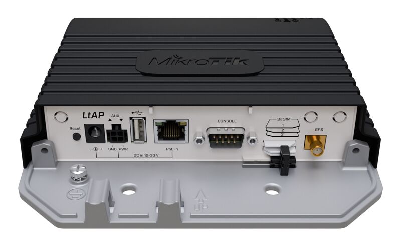
Extension slots and ports
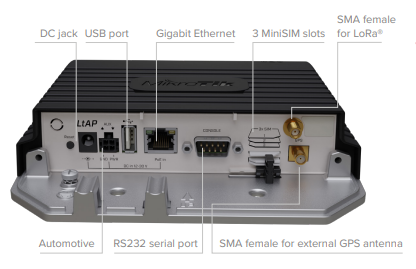
- Built-in 2 GHz wireless access point module, AP/station/bridge/p2p modes are supported. Onboard PIF antennas built-in, as well as MMCX connectors for external antennas (software selectable).
- Two miniPCIe slots and three SIM slots. The first slot (on the bottom) is used by the LTE modem, which is connected to an internal LTE antenna. Second slot (on the upper side) is used by the R11e-LR8G card, which is connected to the external SMA connector
- Built-in GPS module with an external SMA connector.
- Gigabit Ethernet port, supporting automatic cross/straight cable correction (Auto MDI/X). Either straight or crossover cable can be used for connecting to other network devices. The Ethernet port accepts 12-30 V DC powering from a passive PoE injector.
- One DB9 RS232 serial port for serial console access. Configured as 115200 bit/s, 8 data bits, 1 stop bit, no parity.
- One USB 2.0 port.
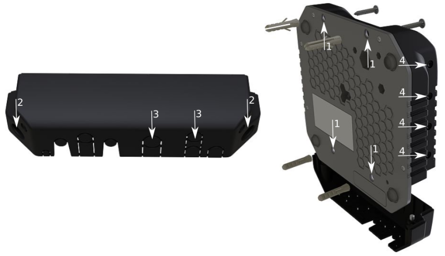
Mounting
- It is possible to attach the device to a wall, using the provided four screws and designed four holes on the unit.
- The ports are protected with a small door, that is held in place with two screws. Remove to access Ethernet ports, antenna connector, SIM slots, etc.
- The door has cut-out places for all available ports, so you can guide through all necessary cables, but please only break out the openings that you will use.
- Several places for external antennas are provided on the case, use an appropriate size drill, to make them available. Be careful and measure the chosen antenna, so that it does not touch the internal PCB board when installed.
The device can be used both indoors and outdoors. The IP rating scale of IP54.
If you intend to mount outdoors, please ensure that any cable openings are directed downwards. The Mounting direction is indicated on the device with an arrow pointing up. Use POE injector and proper grounding. Recommended using Cat6 shielded cable. Warning! This equipment should be installed and operated with a minimum distance of 30 cm between the device and your body. Operation of this equipment in the residential environment could cause radio interference. The device enclosure has places where you can drill openings for external LTE and GPS antennas. Use a drill to make holes that are appropriate for the antenna cable used.
Configuration
We recommend clicking the "Check for updates" button and updating your RouterOS software to the latest version to ensure the best performance and stability. RouterOS includes many configuration options in addition to what is described in this document. We suggest starting here to get yourself accustomed to the possibilities: https://mt.lv/help In case IP connection is not available, the WinBox tool (https://mt.lv/winbox) can be used to connect to the MAC address of the device from the LAN side (all access is blocked from the internet port by default). For recovery purposes, it is possible to boot the device from a network, see the section (link) section part 4;- Please see the picture below for reference on how to place rubber seals for best water protection;
- Reassembly in backorder. Tightening torque for PCB screws 0.3 Nm, case cover/enclosure screws 0.5 Nm.

After you have reinserted the device into the case and secured it with the screws that were removed earlier, slide in the SIM cards from your mobile operator into the SIM slots, with the chips facing as shown on the port label. The slot accepts miniSIM (2FF). SIM slots 2 and 3 apply to the bottom miniPCIe slot and can be switched in RouterOS "/system routerboard sim" menu.
Reset button
- Hold this button during boot time until LED light starts flashing, release the button to reset RouterOS configuration (total 5 seconds).
- Keep holding for 5 more seconds, LED turns solid, release now to turn on CAP mode. The device will now look for a CAPsMAN server (total 10 seconds).
- Or keep holding the button for 5 more seconds until LED turns off, then release it to make the RouterBOARD look for Netinstall servers (total 15 seconds). Regardless of the above option used, the system will load the backup RouterBOOT loader if the button is pressed before power is applied to the device. Useful for RouterBOOT debugging and recovery.
Accessories
Package includes accessories that come with the device:
- K-67 fastening set. Includes four screws 4x25 mm, four dowels 6x30 mm.
- Cable DC ⎓ (H4130-04PDB000R 3 mm 2x2P Housing) to (StripJacket 5 cm+WireEnd Strip/Tin 1 cm) 24 AWG (Black/Red/Blue/Orange) 0.35 m.
- EU/US Switching Power Supply 24 V, 1.2 A, 28.8 W, 86.8%, VI, DC ⎓ cable: 220 cm RA DC plug mod Hor CMC shorter plug.
Operating system support
The device supports RouterOS software with version number v7.11 at or above which is indicated in the RouterOS menu /system resource. Other operating systems have not been tested.
MikroTik mobile app
Use the MikroTik smartphone app to configure your router in the field, or to apply the most basic initial settings for your MikroTik home access point.

- Scan QR code and choose your preferred OS.
- Install and open application.
- By default, the IP address and user name will be already entered.
- Click Connect to establish a connection to your device through a wireless network.
- Choose Quick setup and application will guide you through all basic configuration settings in a couple of easy steps.
To avoid pollution of the environment, please separate the device from household waste and dispose of it in a safe manner, such as in designated waste disposal sites. Familiarize yourself with the procedures for the proper transportation of the equipment to the designated disposal sites in your area.