LHGG LTE7 kit
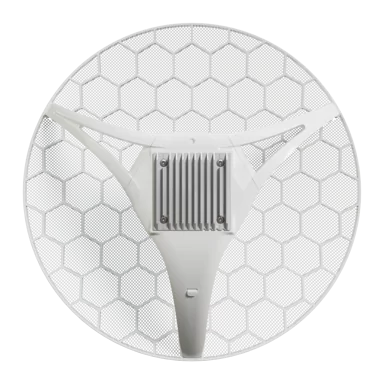
LHGG LTE7 kit (LHGGR&R11e-LTE7)
The new LHGG LTE7 kit upgrades the popular LTE6 model with a CAT7 modem and doubled upload speed, while keeping the proven 17 dBi long-range antenna and rugged grid design – now at a significantly better price.
Safety Warnings
- Before you work on any equipment, be aware of the hazards involved with electrical circuitry, and be familiar with standard practices for preventing accidents. See the LHGG LTE7 kit product page for full specifications and brochures.
- Ultimate disposal of this product should be handled according to all national laws and regulations.
- All installation methods for mounting an access point on any wall surface is subject to the acceptance of local jurisdiction.
- The Installation of the equipment must comply with local and national electrical codes.
- This product is intended to be mounted outdoors on a pole. Read the mounting instructions carefully before beginning installation. Failure to use the correct hardware and configuration or to follow the correct procedures could result in a hazardous situation for people and damage to the system.
- Use only the power supply and accessories approved by the manufacturer, and which can be found in the original packaging of this product.
- Read the installation instructions before connecting the system to the power source.
- We cannot guarantee that no accidents or damage will occur due to the improper use of the device. Use this product with care and operate at your own risk!
- In the case of device failure, disconnect it from power. The fastest way to do so is by unplugging the power plug from the power outlet.
- It is the customer's responsibility to follow local country regulations, including operation within legal frequency channels, output power, cabling requirements, and Dynamic Frequency Selection (DFS) requirements. All MikroTik radio devices must be professionally installed.
- This is a class A device. In a domestic environment, this product might cause radio interference in which case the user might be required to take adequate measures.
Exposure to Radio Frequency Radiation: This MikroTik equipment complies with the FCC, IC, and European Union radiation exposure limits set forth for an uncontrolled environment. This MikroTik device should be installed and operated no closer than 130 centimeters from your body, occupational user, or the general public.
Specifications
| Parameter | Value |
|---|---|
| Product code | LHGGR&R11e-LTE7 |
| Architecture | ARM 64bit |
| CPU | 88F3720 |
| CPU core count | 2 |
| CPU nominal frequency | 800 MHz |
| CPU Threads count | 2 |
| RouterOS license | 3 |
| Operating System | RouterOS v7 |
| Size of RAM | 256 MB |
| Storage size | 16 MB |
| Storage type | FLASH |
| MTBF | Approximately 200'000 hours at 25C |
| Tested ambient temperature | -40°C to 70°C |
| Powering | |
| Number of DC inputs | 1 (PoE-IN) |
| Max power consumption | 8 W |
| Max power consumption without attachments | 8 W |
| PoE in | 802.3af/at |
| Cooling type | Passive |
| PoE in input Voltage | 12-57 V |
| Mobile | |
| 3G Category | R8 (DL: 42.2 Mbps; UL: 5.76 Mbps) |
| 3G bands | 1 (2100 MHz), 3 (1800 MHz), 5 (850 MHz), 8 (900 MHz) |
| LTE Category | 7 (DL: 300 Mbps; UL: 100 Mbps) |
| MIMO DL | 2x2 |
| MIMO UL | 1x1 |
| LTE FDD bands | 1 (2100 MHz), 3 (1800 MHz), 5 (850 MHz), 7 (2600 MHz), 8 (900 MHz), 20 (800 MHz), 28 (700 MHz) |
| LTE TDD bands | 38 (2600 MHz), 40 (2300 MHz), 41 (2500 MHz) |
| TAC | 35312597 |
| Ethernet | |
| 10/100/1000 Ethernet ports | 1 |
| Peripherals | |
| Number of SIM slots | 1 Modem (Micro SIM) |
| MiniPCI-e slots | 1 |
| Other | |
| Mode button | Yes |
| Certification & Approvals | |
| Certification | CE, EAC, ROHS |
| IP | 54 |
Quickstart
- Open the Ethernet port door;
- Insert the Micro SIM card into the slot, with the chip facing UP;
- Connect the device to the included PoE injector with an Ethernet cable to the data+power end;
- Connect the data end of the PoE injector to the computer;
- Connect the power adapter to the PoE injector;
- Configure your device using a web browser through WebFig or the WinBox tool at https://mt.lv/winbox; multiple configuration methods are available to ensure accessibility;
- Access WebFig by opening https://192.168.188.1, and for WinBox, download the tool, navigate to the Neighbors tab, and select the MAC address. The username is "admin" with no password (or, for some models, check user and wireless passwords on the sticker);
- Enter the PIN code, if required by your mobile network operator;
- Select the "Check for updates" button and update RouterOS to the latest version. Must have a valid SIM card inserted and active Internet connection;
- For a manual update of the device, visit mikrotik.com, select your model, and locate the required packages in the "Downloads" section;
- Upload downloaded packages to the WebFig or WinBox "Files" menu and reboot the device;
- By upgrading your RouterOS software to the latest version, you can ensure optimal performance, stability, and security updates;
- Set up your router password.
Case assembly
- Attach the two legs to the LHG case by sliding them onto the respective sides, legs are different and cannot be exchanged (when looking at the product place it that cover for Ethernet port is in front of you, leg marked R is for the right side, leg marked L is for the left side).
- Snap the assembled LHG unit to the grid in the appropriate central location.
- Fix the two legs in place with included two self thread screws (Phillips screwdriver PH2). The package also contains a grounding cable connector and a 5-degree angle adapter, for easier up or downward tilt adjustment.
Opening the case cover
Optional - to access the miniPCIe slot, the opening of the unit top cover is required. As an opening tool, you can use a large size flat head screwdriver or a small coin. Be extremely cautious when opening, because the incorrect opening of the clip can break it off! Mounting and configuration of this device should be done by a qualified person. Follow these steps:
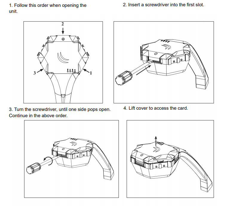
Additional caution when lifting up the cover, do not force it with sharp objects.
miniPCIe slot usage
The device is equipped with a miniPCIe slot and has already installed an LTE7 modem. One SIM slot is provided for use together with a miniPCIe modem. The SIM slot is not used separately. Replacing a miniPCIe module should be done by a qualified person, follow safety precautions when handling electrical equipment:
- Use a wrist grounding strap when unpacking and working with electrical components to avoid electrical discharge (ESD) damage;
- Open the upper cover as shown in instruction previously;
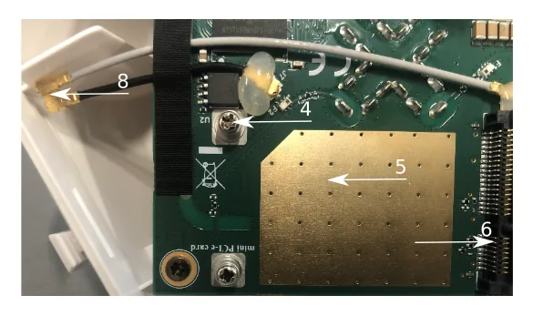
- The antenna is located underneath PCB;
- Locate the miniPCIe slot on the PCB and remove two factory attached screws;
- Attach provided a thick thermal pad to the card, and install the card into miniPCIe slot so that thermal pad is between PCB and card;
- Insert your desired card;
- Secure the card in place using previously removed two screws;
- Attach the grey uFL connector to the MAIN antenna connector of the modem, attach the black cable to the secondary (or AUX) connector;
- Attach a thinner thermal pad to the top of the card;
- Reassemble. After reassembly, slide in the SIM card from your mobile operator into the SIM slot, with the chips facing up as shown on the port label. The slot accepts MicroSIM (3FF).
Powering
The device can be powered from 12-57 V 802.3af/at sources and also Passive PoE injectors (one power supply and PoE injector are included). Maximum power consumption 8 W.
Connecting to a PoE Adapter
- Connect the Ethernet cable from the device to the PoE+DATA port of the PoE adapter;
- Connect an Ethernet cable from your local network (LAN) to the PoE adapter;
- Connect the power cord to the adapter, and then plug the power cord into a power outlet.
Mounting
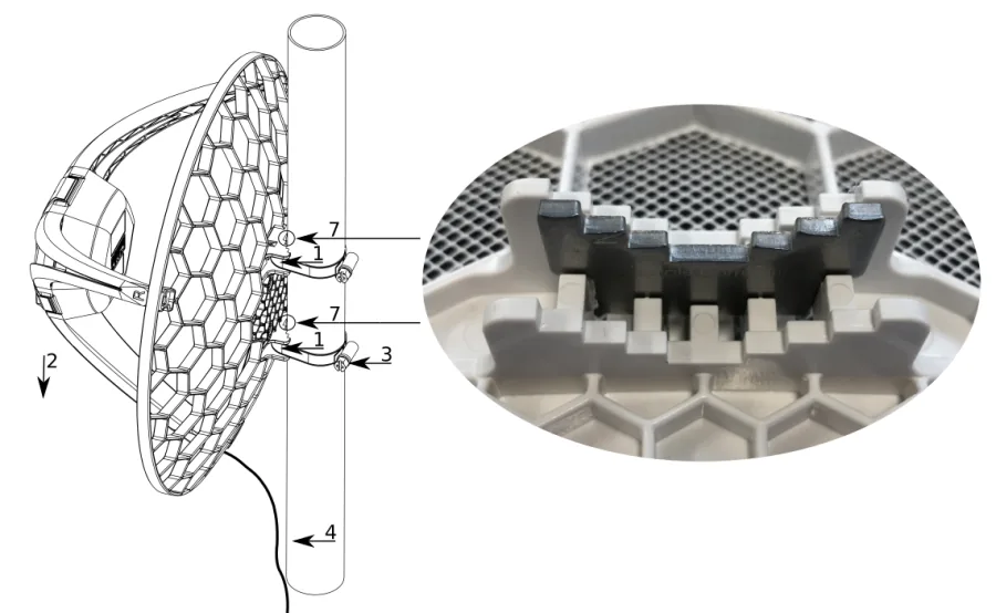
- Slide the included metallic mounting rings into the two slots on the back of the antenna dish.
- Attach the unit to a pole, with the Ethernet port pointing downward.
- Use a PH2 screwdriver to tighten the rings.
- Fix the Ethernet cable to the pole using zip ties, less than one meter from the unit, to avoid the cable being pulled out of the port.
- Check mounting angle and positioning.
- Optional: If required, before mounting the unit, you can insert the included 5-degree adjustment adapter into the top or bottom slot where the mounting ring is inserted. This will create an additional upward or downward angle when the unit is tightened to a vertical pole.
- Insert a 5-degree angle adapter to one of the slots and remount the unit. When mounting outdoors, ensure that any cable openings are directed downwards. Use POE injector and proper grounding, this device has a specially designed grounding connector under the port cover. Recommended using shielded Cat5/6 cable. The IP rating scale for this device is IP54. Warning! This equipment should be installed and operated with a minimum distance of 120 cm between the device and your body. Operation of this equipment in the residential environment could cause radio interference.
Configuration
Once logged in, you should select the "Check for updates" button in the QuickSet menu, as updating your RouterOS software to the latest version ensures the best performance and stability. For wireless models, make sure you have selected the country where the device will be used, to conform with local regulations. RouterOS includes many configuration options in addition to what is described in this document. We suggest starting here to get yourself accustomed to the possibilities: https://mt.lv/help In case IP connection is not available, the WinBox tool (https://mt.lv/winbox) can be used to connect to the MAC address of the device from the LAN side (all access is blocked from the Internet port by default).
Accessories
Package includes the following accessories and parts that come with the device:
- 24V 0.8A power adapter;
- Gigabit PoE injector;
- Hose clamp 2;
- K-LHG screw kit.
Extension slots and ports
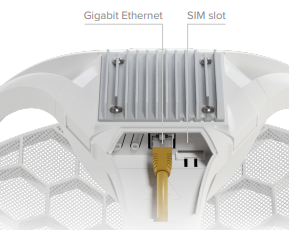
- One Gigabit Ethernet port, supporting automatic cross/straight cable correction (Auto MDI/X). Either straight or crossover cable can be used for connecting to other network devices. The Ethernet port accepts 12-57 V DC powering from a PoE injector.
- MiniPCIe slot with LTE7 modem.
- SIM slot (can't be used separately).
Reset button
The reset button has three functions:
- Hold this button during boot time until LED light starts flashing, release the button to reset RouterOS configuration (total 5 seconds);
- Keep holding for 5 more seconds, LED turns solid, release now to turn on CAP mode. The device will now look for a CAPsMAN server (total 10 seconds);
- Or Keep holding the button for 5 more seconds until LED turns off, then release it to make the RouterBOARD look for Netinstall servers (total 15 seconds); Regardless of the above option used, the system will load the backup RouterBOOT loader if the button is pressed before power is applied to the device. Useful for RouterBOOT debugging and recovery.
Mode button
The action of the mode button can be configured from RouterOS software to execute any user-supplied RouterOS script. You can also disable this button. The mode button can be configured in RouterOS menu /system routerboard mode-button.
Included parts
- 24V 0.8A power adapter
- Gigabit PoE injector
- Hose clamp 2
- K-LHG screw kit
Operating system support
The device supports RouterOS v7 and above. The specific factory-installed version is listed in /system resource. Other operating systems have not been tested.
To avoid pollution of the environment, separate the device from household waste and dispose of it in a safe manner, such as in designated waste disposal sites. Familiarize yourself with the procedures for the proper transportation of the equipment to the designated disposal sites in your area.