L14G-2ax-BT5-LR8&EG800K (KNOT Gateway LR8)
This guide can be downloaded as a PDF file.
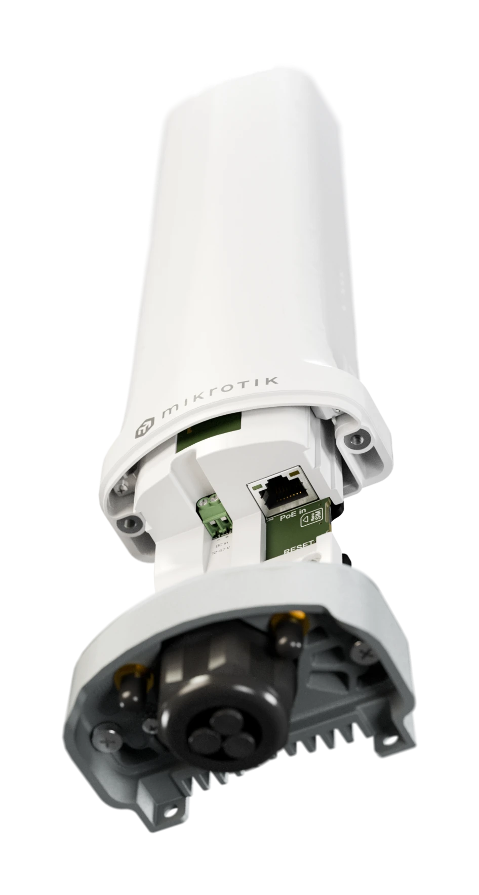
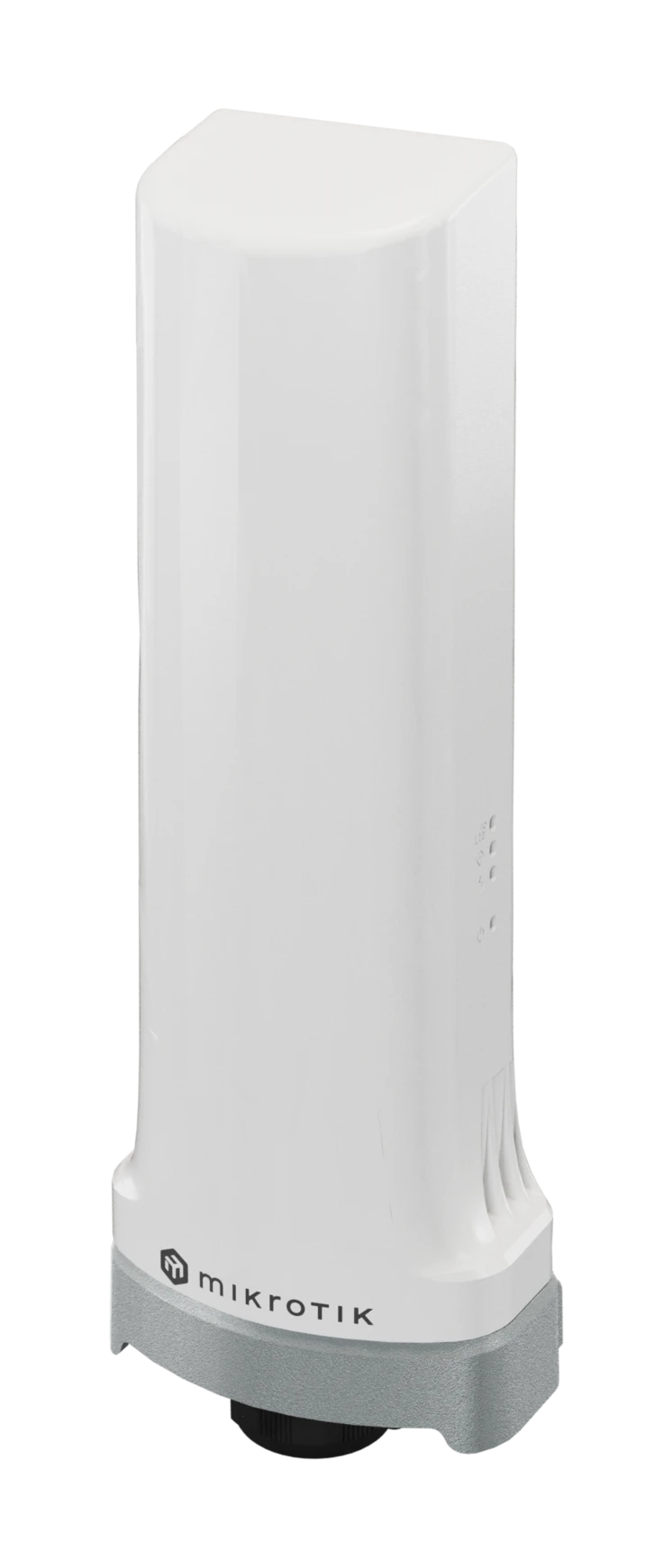
KNOT Gateway LR8 (L14G-2ax-BT5-LR8&EG800K)
KNOT Gateway LR8 – connectivity that fits anywhere. Originally designed for coffee and vending machines – perfect for all kinds of industrial automation. See the KNOT Gateway LR8 product page for full specifications and brochures.
Safety Warnings
- Before you work on any equipment, be aware of the hazards involved with electrical circuitry, and be familiar with standard practices for preventing accidents.
- Ultimate disposal of this product should be handled according to all national laws and regulations.
- The Installation of the equipment must comply with local and national electrical codes.
- This product is intended to be installed outdoors, on a wall or pole. Please read the mounting instructions carefully before beginning installation. Failure to use the correct hardware or to follow the correct procedures could result in a hazardous situation for people and damage to the system.
- Use only the power supply and accessories approved by the manufacturer, and which can be found in the original packaging of this product.
- Read the installation instructions before connecting the system to the power source.
- We cannot guarantee that no accidents or damage will occur due to the improper use of the device. Please use this product with care and operate at your own risk!
- In the case of device failure, please disconnect it from power. The fastest way to do so is by unplugging the power plug from the power outlet.
- It is the customer's responsibility to follow local country regulations, including operation within legal frequency channels, output power, cabling requirements, and Dynamic Frequency Selection (DFS) requirements. All MikroTik radio devices must be professionally installed.
Exposure to Radio Frequency Radiation: This MikroTik equipment complies with the FCC, IC, and European Union radiation exposure limits set forth for an uncontrolled environment. This MikroTik device should be installed and operated no closer than 20 centimeters from your body, occupational user, or the general public.
Specifications
| Parameters | Description |
|---|---|
| Product Code | L14G-2ax-BT5-LR8&EG800K |
| Architecture | ARM 64-bit |
| CPU | IPQ-5010, 2 core, 800 MHz |
| RAM / Storage | 256 MB RAM / 128 MB NAND |
| OS | RouterOS v7, License Level 4 |
| Mobile: LTE | Category 1 bis (10 Mbps ↓ / 5 Mbps ↑) |
| MIMO | DL 1×1, UL 1×1 |
| LTE FDD Bands | 1 (2100 MHz), 3 (1800 MHz), 5 (850 MHz), 7 (2600 MHz), 8 (900 MHz), 20 (800 MHz), 28 (700 MHz) |
| TAC | 86684606 |
| Wireless | 2.4 GHz 802.11b/g/n/ax, Wi-Fi 6, 1 chain, 287 Mbit/s, 3.9 dBi |
| Bluetooth | 5.1 |
| Ethernet | 1 × 1 GbE RJ45 (PoE-in 802.3af/at, 18-57 V) |
| SIM | 1 × Nano-SIM & eSIM |
| Power | PoE-in (18-57 V) or 2-pin terminal (12-57 V), max 9 W |
| Cooling | Passive |
| Dimensions | 254 × 88 × 57 mm |
| Operating Temp. | –40 °C … +50 °C |
| MTBF | Approximately 200,000 hours at 25 °C |
| IP | IP66 |
Quickstart
- Ensure your Internet Service Provider (ISP) allows hardware changes and automatically assigns an IP address;
- Connect the ISP cable to the Ethernet1 port;
- Connect the device to the power source;
- Connect to the device through any of the ports, excluding Ethernet1, or the wireless network "MikroTik-..." (check the wireless passwords on the sticker);
- Establish a connection using a mobile application. Alternatively, use WebFig in a web browser or the WinBox configuration tool at https://mt.lv/winbox. Multiple configuration methods are available to ensure accessibility;
- Start configuration within the chosen tool, using the default IP address
192.168.88.1. If the IP address is unavailable, use WinBox and choose the "Neighbors" tab to find the device; - Proceed to connect using the MAC address. The username is "admin", and there is no password (or, for some models, check user and wireless passwords on the sticker);
- Click the "Check for updates" button and update RouterOS to the latest version;
- For a manual update of the device, visit mikrotik.com, select your model, and locate the required packages in the "Downloads" section;
- Upload downloaded packages to the WebFig or WinBox "Files" menu and reboot the device;
- By upgrading your RouterOS software to the latest version, you can ensure optimal performance, stability, and security updates;
- In the Quick Set, WISP AP menu, choose your country to apply country regulation settings;
- Set up your wireless network password;
- Set up your router password.
Mounting
The device is designed for outdoor use and can be mounted on either a wall or a pole.
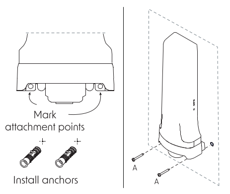
To mount the device on the wall
- Drill 6 mm holes corresponding to the mounting points on the back of the device, including additional holes for the security/locking points;
- Insert screws into the anchors, leaving approximately 10 mm of the screw heads exposed;
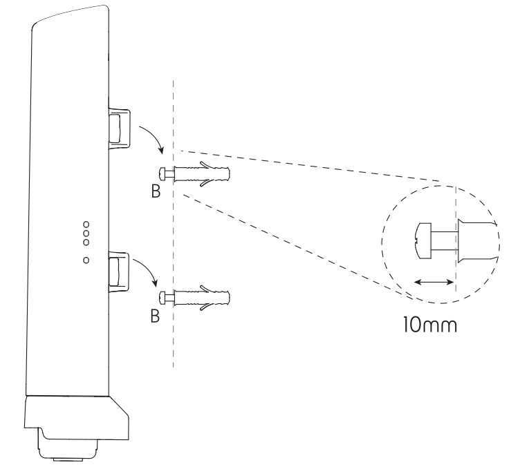
- Position the device and align it with the mounting points;
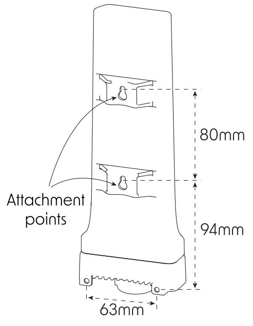
- Secure the device to the wall by tightening the screws.
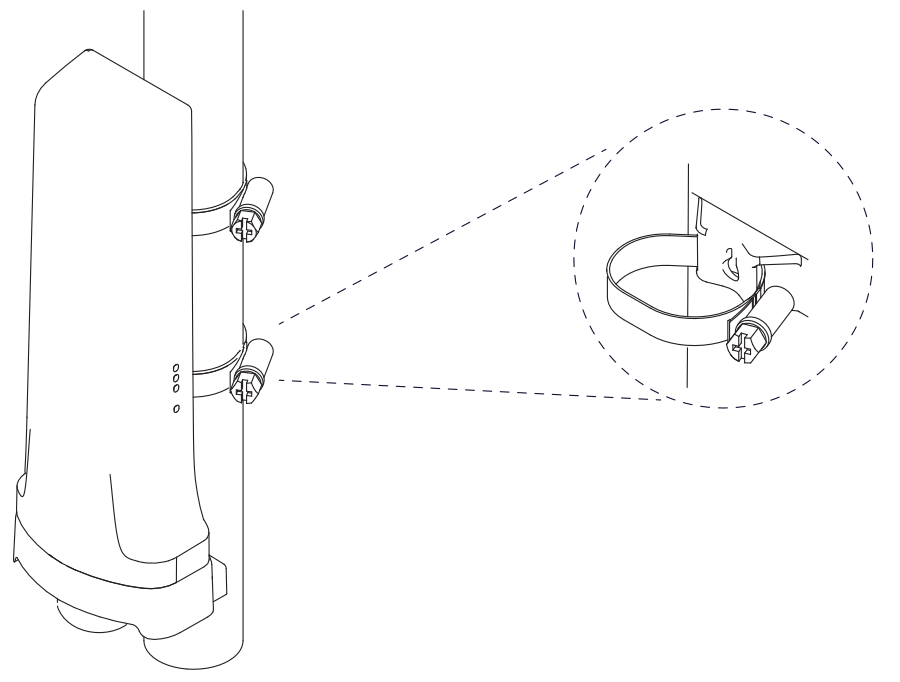
To mount the device on a pole
- Insert the hose clamps through the holes in the mounting brackets;
- Position the device against the pole and wrap the clamps around the pole;
- Tighten the clamps to secure the device firmly in place.
This equipment should be installed and operated with a minimum distance of 20 cm between the device and your body. The operation of this equipment in the residential environment could cause radio interference.
Mounting and configuration of this device should be done by a qualified person.
Powering
- 2-pin terminal accepts 12-57 V DC⎓;
- Ethernet port accepts 802.3af/at Power over Ethernet 18-57 V DC.
The maximum power consumption can reach up to 9 W.
Connecting to a PoE Adapter
- Connect an Ethernet cable from the device to the PoE + DATA port of the PoE adapter;
- Connect an Ethernet cable from your local network (LAN) to the DATA port of the PoE adapter;
- Connect the power cord to the adapter, then plug it into a power outlet.
Cellular modem configuration
Sub-menu: /interface lte
For band selection, roaming, or advanced options, please refer to the LTE/5G manual.
Reset button
The reset button has three functions:
- Hold this button during boot time until the green LED light starts flashing, release the button to reset RouterOS configuration.
- Keep holding the reset button until the LED turns solid, then release it to enable CAP mode. The device will then start searching for a CAPsMAN server.
- To reinstall RouterOS using the Netinstall utility, enter the device into BOOTP mode. Two booter options are available: the Regular Booter and the Backup Booter. It is recommended to verify both options in case one does not work.
- Regular Booter: To enter etherboot mode, press the Reset button after powering on the device and waiting 1–2 seconds.
- Backup Booter: Power off the device. Press and hold the Reset button, then power on the device. Wait for the LED sequence (blinking → steady → off), then release the button. The device will boot into BOOTP mode, ready for RouterOS reinstallation via Netinstall.
Regardless of the above option used, the system will load the backup RouterBOOT loader if the button is pressed before power is applied to the device. Useful for RouterBOOT debugging and recovery.
Accessories
The package includes the following accessories that come with the device:
- KNOT Gateway LR8.
- 24 V, 0.5 A power adapter.
- Gigabit PoE injector.
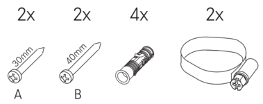
- K-66 fastening set.
- Hose clamp (2 pcs).
Operating system support
The device supports RouterOS v7 and above. The specific factory-installed version is listed in /system resource. Other operating systems have not been tested.