Neighbor Discovery
CLI reference:/ip/neighbor/ip/neighbor/discovery-settings/ip/neighbor/lldp
Neighbor Discovery protocols allow you to find devices compatible with MNDP (MikroTik Neighbor Discovery Protocol), CDP (Cisco Discovery Protocol), or LLDP (Link Layer Discovery Protocol) in the Layer 2 broadcast domain. They can be used to map out your network.
/ip/neighbor lists all discovered neighbors, whichever of the protocols announced them (the discovered-by value shows which). The read-only /ip/neighbor/lldp menu shows only LLDP-discovered entries. All read-only neighbor parameters are described in the /ip/neighbor CLI reference:
[admin@MikroTik] > /ip/neighbor/print where identity="Router-A"
Columns: INTERFACE, ADDRESS4, ADDRESS6, MAC-ADDRESS
# INTERFACE ADDRESS4 ADDRESS6 MAC-ADDRESS
0 ether2 192.168.88.24 fe80::de2c:6eff:fee7:106a DC:2C:6E:E7:10:6B
The neighbor list keeps entries while the device announces itself. A device announces its presence every 30 seconds (the default discover-interval); when announcements stop, the entry is dropped after it ages out. The lldpRemTable SNMP table reports only neighbors discovered through LLDP; entries discovered exclusively by CDP or MNDP are not part of the SNMP LLDP-MIB.
View and configure discovery in WinBox
Open IP > Neighbors to see discovered devices and the interfaces through which they were found. Select the LLDP tab for LLDP-only entries. To configure discovery, select Discovery Settings in the right panel:
- Select the interface list in Interface. This corresponds to
discover-interface-list; choose a list containing the interfaces that should participate in discovery. - Select the required Protocol checkboxes and review Mode, which controls whether discovery transmits, receives, or does both. Select OK to save the settings.
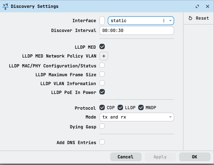
The screenshot shows an existing configuration. Choose the interface list for your network rather than copying its selection.
Choose which interfaces participate
Discovery settings are configured in the /ip/neighbor/discovery-settings menu:
/ip/neighbor/discovery-settings/print
Discovery runs on the interfaces of the discover-interface-list interface list (static by default). An interface in the list both announces the router (sends discovery packets) and accepts neighbors heard on it. Removing an interface from the list disables discovery on it in both directions: the router no longer announces itself there and stops accepting neighbors heard on it. Setting the list to none switches discovery off altogether: announcements stop (on other devices this router's entries age out — their age value keeps growing until the entries disappear) and this router's own neighbor list empties. To only stop announcing but keep seeing neighbors (for example on a WAN), set mode=rx-only.
Neighbor discovery works on individual slave interfaces. When a master interface (bonding or bridge) is included in the discovery interface list, all its slave interfaces participate automatically. The neighbor list shows both the master interface and the slave interface on which the announcement arrived (see the ether2 + bridge entry in the example above). To allow neighbor discovery only on some slave interfaces, include only those slave interfaces in the list and make sure the master interface is not included:
/interface/bonding add name=bond1 slaves=ether5,ether6
/interface/list add name=only-ether5
/interface/list/member add interface=ether5 list=only-ether5
/ip/neighbor/discovery-settings set discover-interface-list=only-ether5
LLDP-MED Network Policy VLAN example
This example configures a switch port for a VoIP phone that daisy-chains a PC. The phone uses tagged traffic for voice, assigned through the LLDP-MED Network Policy TLV. The PC uses untagged traffic, which is assigned to a different VLAN by the bridge port PVID.
In this setup:
- ether1 is the upstream trunk port, carrying all VLANs tagged to a router.
- ether2 is the phone port. The VoIP phone connects directly, and the PC connects through the phone.
- Voice traffic uses VLAN 100 (tagged), advertised through
lldp-med-net-policy-vlan. - Data traffic from the PC uses VLAN 200 (untagged on the phone port), assigned by the bridge port
pvid.
- Voice traffic uses VLAN 100 (tagged), advertised through
Create the bridge and add the ports:
/interface/bridge
add name=bridge1 frame-types=admit-only--tagged
/interface/bridge/port
add bridge=bridge1 interface=ether1 frame-types=admit-only--tagged
add bridge=bridge1 interface=ether2 pvid=200
Create the bridge VLAN table. The trunk port carries both VLANs tagged. The phone port carries the voice VLAN as tagged. The data VLAN for the PC is assigned by the bridge port pvid, which dynamically adds an untagged membership — no explicit untagged=ether2 is needed:
/interface/bridge/vlan
add bridge=bridge1 tagged=ether1,ether2 vlan-ids=100
add bridge=bridge1 tagged=ether1 vlan-ids=200
Enable LLDP-MED and set the voice VLAN. Disable CDP to avoid interference with LLDP-MED:
/ip/neighbor/discovery-settings
set lldp-med=yes lldp-med-net-policy-vlan=100 protocol=lldp,mndp
Enable VLAN filtering on the bridge:
/interface/bridge/set bridge1 vlan-filtering=yes
The LLDP-MED Network Policy TLV is sent only on interfaces where an LLDP-MED-capable device is discovered. It is not broadcast on interfaces without MED-capable neighbors.
For more details on bridge VLAN configuration, see Bridge VLAN Filtering.
LLDP
Depending on RouterOS configuration, different type-length-values (TLVs) can be sent in the LLDP message. This includes:
- Chassis ID (MAC address).
- Port ID (interface name).
- Time To Live.
- System Name (system identity).
- System Description (platform - MikroTik, software version - RouterOS version, hardware name - RouterBoard name).
- Management Address (all IP addresses configured on the port).
- System Capabilities (enabled system capabilities, for example bridge or router).
- Port Description (combined interface name like "bridge/ether1" if the sending interface is part of a bridge or bond, or interface name the same as Port ID).
- IEEE 802.1 Port VLAN ID.
- IEEE 802.1 Port And Protocol VLAN ID.
- IEEE 802.1 VLAN Name.
- IEEE 802.3 MAC/PHY Configuration/Status.
- IEEE 802.3 Power Via MDI.
- IEEE 802.3 Maximum Frame Size.
- LLDP-MED Media Capabilities (list of MED capabilities).
- LLDP-MED Network Policy (assigned VLAN ID for voice traffic).
- LLDP-MED Extended Power via MDI.
- End of LLDPDU.
Technical details
- Devices announce every
discover-interval(30s by default); on the receiving side an entry is removed when no announcement arrives in time. CDP and LLDP announcements carry a TTL of(discover-interval * 4) + 1. - The announcement contents and optional TLVs are controlled by the
/ip/neighbor/discovery-settingsparameters, including PoE TLVs (lldp-poe-power,lldp-poe-in-power) and DCBX (lldp-dcbx). dying-gaspsends a discovery packet with TTL=0 before a graceful reboot, shutdown or upgrade so neighbors remove the entry immediately.add-dns-entriescreates dynamic DNS entries for discovered neighbors by identity; see DNS.
For all parameters and read-only values, see the /ip/neighbor, /ip/neighbor/discovery-settings and /ip/neighbor/lldp CLI reference pages.