TG-LR setup guide
Quickstart Guide
-
Register device on LoRaWAN network server. Use tg-lrx2-2.0-ul-dec.js payload decoder script if device model not supported.
-
Optionally deploy Grafana + Influx (telemetry_hub.zip) docker services for device capability evaluation.
-
Activate device by holding magnet near reed switch and wait for 2x LED blinks (~1.5s).
Functionality
New device is in SHUTDOWN mode. To activate use magnet switch commands.
Table 1 Models
| Model | Description | Sensors |
|---|---|---|
| TG-LR82 | LoRaWAN 1.0.4 Class A, B, 863.0 - 869.0 MHz band. | TMP116N, HDC2010, LIS2DW12 |
| TG-LR92 | LoRaWAN 1.0.4 Class A, B, 900.0 - 928.0 MHz band. | TMP116N, HDC2010, LIS2DW12 |
Table 2 Bands
| Numeric code | Name | Description |
|---|---|---|
| 1 | BAND_1GHz | Sub-GHz operating band. Frequency range is based on device Model. |
| 2 | BAND_2GHz | 2.4GHz ISM band. |
Table 3 Operating modes
| Numeric code | Mode | Description |
|---|---|---|
| 0 | SHUTDOWN | Device in low power mode with all functionality disabled. |
| 1 | RUN | Device joins network and sends uplinks based on current profile and configuration. |
Table 4 Supported regions
| X-Y Code | downlink | Common Name | TG-LR82 | TG-LR92 |
|---|---|---|---|---|
| 1-1 | 1 | EU868 | Yes | |
| 2-1 | 2 | AS923_GRP1 | Yes | |
| 3-1 | 3 | US915 | Yes | |
| 4-1 | 4 | AU915 | Yes | |
| WW2G4 | Yes | Yes | ||
| 6-1 | 7 | AS923_GRP2 | Yes | |
| 7-1 | 8 | AS923_GRP3 | Yes | |
| 8-1 | 9 | IN865 | Yes | |
| 9-1 | 10 | KR920 | Yes |
LoRaWAN
Device supports Class A and B, and can operate in two frequency bands: BAND_1GHz and BAND_2GHz. User can configure periodic link check, MAC time synchronization (DeviceTimeReq) and network ADR.
Join Procedure
Once activated (RUN) device will attempt to join network. Device sends Join-Request on primary band and if Join-Accept is not received it will wait back-off interval and send next Join-Request on secondary band if enabled, otherwise primary-band again.
Join attempt interval depends on time on air for last Join-Request and total join time. See 1 section 7. If last join request used slower data rate - expect longer interval.
Join configuration commands: lora primary-band, lora second-band, lora join-cfg. See Command Encoding on how to convert text commands to binary encoding for downlink.
Link Check
Once device has joined network optional periodic link check can be performed. Link check can be configured specifically for each band using lora link-chk. If link check fails device leaves network and restarts join procedure.
Any network downlink will restart link check timer to prevent unnecessary LinkCheckReq.
Time Synchronization
Device supports optional time synchronization using DeviceTimeReq MAC command. See command lora clk-sync for configuration parameters or to request immediate synchronization.
Class B
Device supports Class B operation. Class B operation can be either manually requested using lora class or device can be configured to automatically switch to class B on network join using lora cfg-class-b.
ADR Configuration
It is possible to disable network ADR and set fixed data rate using lora adr-cfg.
Leaving Network
In case of Link Check or confirmed uplink failure device leaves network and restarts join procedure.
Credentials
Device has factory configured default credentials that come with each device: DevEUI, JoinEUI, AppKey.
DevEUI and JoinEUI are IEEE 64-bit EUI (2) written MSB first. On air byte order is LSB first. See 1 section 6.2.5.
AppKey is 16 byte AES128 encryption key and is written as stored in device memory. AppKey must be kept secret!
To change JoinEUI and AppKey use commands: lora join-eui, lora net-key and lora cred. Commands lora join-eui and lora net-key can be issued in any order and multiple times to write new pending join credentials.
Once new pending credentials are written “lora cred 600,1” or “app reset 0” can be executed to attempt join with new credentials. If new credentials are not confirmed by join accept device will revert to previous. See LORA-275, LORA-276 for know issues!
Example sequence where JoinEUI and AppKey are written and join is attempted:
lora join-eui 87904163,0x00,0x16,0xC0,0x01,0xFF,0xFE,0x00,0x00
lora net-key 87904163,0x00,0x01,0x02,0x03,0x04,0x05,0x06,0x07,0x08,0x09,0x0A,0x0B,0x0C,0x0D,0x0E,0x0F
lora cred 600
app reset 0
// device reboots and attempts join using new credentials with 600s timeout
JoinEUI from previous example can be copy/pasted as is 00 16 C0 01 FF FE 00 00 to register new device. lora join-eui parameters are MSB first.
Executing lora cred <confirm-timeout-s>,87904163 will force confirm credentials without verification join attempt! You may lose access to the device!
Uplink Messages
Each LoRaWAN uplink message is formed by placing pending Data Frames ID and its contents in FPort and FRMPayload fields. All pending frames are packed in ascending order and differential encoding is used for IDs.
See tg-lrx2-2.0-ul-dec.js script for frame encoding details. This script can be used as is in application server payload decoders.
Telemetry
Device Profiles
Device has 6 configurable profiles. Each profile stores independent sensor and uplink send configuration. This allows device to quickly change operating characteristics without requiring costly downlink configuration messages. Profile can be switched using Device Commands, magnet or even based on evaluated Data Rules. For instance switching between periodic keepalive mode with uplinks few times per day to more rapid telemetry every few minutes.
MikroTik can support your specific use case, new devices with custom default configuration are available.
Devices come preconfigured with evaluation configuration to showcase some of possible use case:
Table 5 Default profile configuration
| Profile Number | Name | Description |
|---|---|---|
| 0 | Sensor Telemetry | Send current-state, device-orientation every 5 minutes. Send remaining telemetry every 60 minutes. |
| 1 | Activity Monitor | Send activity, full-activity, current-state every 60 min and send activity_state events on activity idle transition. |
| 2 | Magnet Switch | Send mag-switch, current-state, device-events every 60 minutes and send mag_sw_cnt event when magnet is removed for at least 15 seconds. Save up to 10 events. |
| 3 | Orientation | Send current-state, device-events, device-orientation every 60 minutes. Send device-orientation frame in case of fast rotation by 30 degrees after idle ~30 seconds. Send angle_1 event in case of specific orientation: V=(0,1,1). Save up to 3 events. |
| 4 | Asset Monitor | Send asset healt info every 3h with different frames based on events. |
| 5 | Empty |
See default-cfg.txt for exact factory default configuration commands.
Configuring Sensors
Sampling Intervals
Periodic temperature, humidity and battery voltage sampling can be configured for specific use cases using data poll-cfg command. Device can sample data at a higher rate than uplink frames are sent. This gives opportunity to send average values or to perform rule based decisions. Since sampling interval influences device power consumption this can be leveraged to improve lifetime.
Averaging
Device also tracks average of sampled values in: temperature_ema, humidity_ema, battery_mv_ema, angle_ema. Command data ema-cfg configures exponential moving average (EMA) period and optionally can send EMA values in current-state, dev-health, device-orientation if send-ema-* is enabled.
Count parameters temp-cnt, humid-cnt, bat-cnt, orient-cnt in data ema-cfg determine coefficient a used for moving average calculation. Moving EMA is calculated based on previous value ema and new value sample as:
ema(t) = sample(t) * a + ema(t-1) * (1 - a)
To get approximate time constant t of EMA you need to use sampling intervals configured by data poll-cfg and data orient-cfg (interval) and respective count parameter (N):
t ~ (N + 1) * interval / 2
To get required count parameter value for data ema-cfg:
N ~ 2 * t / interval - 1
Example:
Temperature sampling interval th-poll-int is configured to 30s using data poll-cfg. To configure EMA with time constant t ~ 60 minutes:
temp-cnt = 2 * 3600 / 30 - 1 = 239
Assuming profile #0 is used and we don’t want to change other parameters we need to send command:
data ema-cfg 1,239
Histogram
All periodic samples are added to temperature and humidity histograms. Histograms can be used in addition to regular telemetry or simply stand alone to monitor temperature and humidity distribution. Configure bins and epoch intervals using data temp-histo-cfg, data humid-histo-cfg commands and/or enable temp-histogram, humid-histogram frames. All histogram frames contain epoch number to detect histogram counter reset. Since frame size is limited to 1B per bin, if internal bin counter value is above 255 histogram will be normalized (probability type) for uplink.
Example configuration:
data temp-histo-cfg 1,86400,0,0,1,1,-10,0,10,15,17.5,20,22.5,25.0,30
data humid-histo-cfg 1,86400,0,0,1,1,10,20,30,40,50,60,70,80,90
Orientation
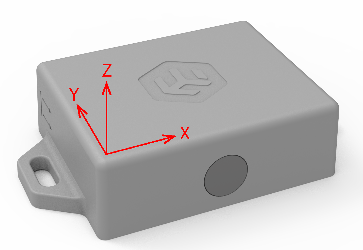
Fig. 1 Device accelerometer axis.
Periodic device 3D orientation sampling relative to Earth can be configured using command: data orient-cfg. In addition 3 user orientation vectors ref-1, ref-2, ref-3 can be configured to detect specific device orientations. User variables angle_1, angle_2, angle_3 contain current angle between device last sampled orientation and user defined vector. These variables can be used in Data Rules to trigger on specific orientation. angle_ema is angle between last sampled device orientation and EMA value of samples. In addition coarse orientation is also available with major_axis_orientation variable.
Table 6 major_axis_orientation description
| Value | Numeric code | Description |
|---|---|---|
| XH | 0 | X up |
| HL | 1 | X down |
| YH | 2 | Y up |
| YL | 3 | Y down |
| ZH | 4 | Z up |
| ZL | 5 | Z down |
| DISABLED | 7 | sensor disabled |
Coarse orientation has advantage that it is sent in current-state frame.
Activity Monitor
Device has activity monitoring service based on accelerometer. This service will automatically manage simple state machine that determines movement/activity. activity_s, high_activity_s, total_activity_s count accumulated time in each state activity_state, activity_state_etm hold state information.
Command data activity-cfg can be used to configure mode and thresholds for activity monitoring. data activity-cal can be used to automatically perform calibration for specific mode.
level1-th and level2-th units are 1/64 * 2G irrespective of other accelerometer settings (like in data acc-cfg). level2-cnt is internally computed and not user configurable. level2-cnt is always in range 7..15 and calculated as:
level2-cnt = 7 + round((1 - ((level2-th - level1-th - 1) / 61)) * 8)
Table 7 activity_state description
| Numeric code | Value |
|---|---|
| 0 | IDLE |
| 1 | LOW |
| 2 | HIGH |
| 3 | DISABLED |
Single Mode
Mode in data activity-cfg is set to single.
-
If accelerometer sample value in any axis is above level1-th device transitions from IDLE to LOW state.
-
If all samples for at least 1.3s are below level1-th device transitions from LOW to IDLE state.
Example to set profile #0 single mode with threshold 0.25G:
data activity-cfg 1,1,8,63
Dual Mode
Mode in data activity-cfg is set to dual.
In dual mode LOW state has two sub states: LOW1 and LOW2 that both represent LOW. Device will report LOW state during both of these and actvity counter values are incremented as if in LOW state. Only difference is transition logic between these states.
Table 8 activity_state dual mode state transitions
| Current | Next | Condition |
|---|---|---|
| IDLE | LOW2 | sample > level1-th |
| LOW2 | LOW1 | sample < level2-th at least 5s |
| LOW1 | LOW2 | sample > level1-th |
| LOW2 | HIGH | sample > level2-th at least level2-cnt times |
| LOW1 | IDLE | sample < level1-th at least 5s |
| HIGH | LOW1 | sample < level2-th at least 5s |
Example to set profile #0 dual mode with thresholds 0.25G and 0.5G:
data activity-cfg 1,2,8,16
Calibration
In addition to manually configuring level1-th and level2-th there is activity calibration functionality. Executing command data activity-cal will perform auto calibration of cal-level. level-one will calibrate level1-th and level-two will calibrate level2-th for all profiles selected in profile-mask. For dual mode you can run level-one and level-two in sequence. Calibration time is 15s. This functionality is mostly suited for periodic motion/vibration.
It may be useful to enable LED during calibration procedure or activity monitor testing to ensure correct operation.
Example to calibrate profile #0 with single level activity monitor:
Activity calibration with orientation enabled causes fault and device reboot. Disable using data orient-cfg before calibration and re-enable after finished. See LORA-279.
-
Place device in environment with periodic motion/activity to calibrate.
-
Send commands:
data activity-cfg 1,1,,,1
data activity-cal 1,1,1
-
Observe LED periodic blink 2x/1.5s for ~ 15s.
-
Test motion detection. During LOW activity device will blink LED 3x/1s.
-
If calibration results are acceptable send command to disable LED:
data activity-cfg 1,,,,0
Example to calibrate profile #0 with dual level activity monitor:
-
Place device in environment with periodic motion/activity for level 1 calibration.
-
Send commands:
data activity-cfg 1,2,,,1
data activity-cal 1,1,1
-
Observe LED periodic blink 2x/1.5s for ~ 15s.
-
Place device in environment for level 2 calibration.
-
Send commands to calibrate level 2:
data activity-cal 1,2,1
-
Observe LED periodic blink 2x/1.5s for ~ 15s.
-
Test motion detection. During HIGH activity device will blink LED 6x/1s.
-
If calibration results are acceptable send command to disable LED:
data activity-cfg 1,,,,0
After calibration level1-th and level2-th can be manually changed using command data activity-cfg.
Impact and Free fall
Command data acc-cfg can be used to configure device accelerometer for basic impact and free-fall detection. Frames: motion-events, impact-count contain relevant data fields. current-state contains impact_evnt, free_fall_evnt flags that indicate new event. These can be used if explicit read is preferred.
Variables impact_cnt, impact_cnt_x, impact_cnt_y, impact_cnt_z, impact_etm, free_fall_cnt, free_fall_etm allow rule based logic.
If Activity Monitor is enabled impact and free fall detection can’t be used and will be ignored.
Data Rules
Up to 32 custom user rules are configurable using commands: data set-rule, data del-rule. Rules have test expression, optional input rules and actions to perform.
Command syntax to add or override rules:
data set-rule [<rule-num>],<test-expr>,[<input-expr>],[<switch-profile>],[<make-event-0>],[<make-event-1>], [<make-event-2>],[<make-event-3>],[<send-frame-0>],[<send-frame-1>],[<send-frame-2>],[<send-frame-3>],[<clr-timer-mask>]
Test Expression
<test-expr>: [^] variable-type <operator> <argument>
| [^] | use variable absolute value in expression |
|---|---|
| variable-type | variable name or ID |
| <operator> | >, >=, <, <=, ==, !=, % |
| <argument> | numeric value |
Example:
data set-rule 0,profile == 0
data set-rule 1,^temperature > 30.55
data set-rule 2,impact_etm < 60
Same rules can be given using User Variables numeric IDs:
data set-rule 0,0 == 0
data set-rule 1,^8 > 30.55
data set-rule 2,24 < 60
Input Expression
Input expression is used if rule needs to depend on result of other rules. This allows constructing sophisticated logic based on multiple test expressions.
<input-expr>: [&][|][!]<input-rule>[<]
| [&] | logical AND of <rule-num> and <input-rule> |
|---|---|
| [|] | logical OR of <rule-num> and <input-rule> |
| [!] | logical NOT of input value |
| <input-rule> | rule number to add as a input |
| [<] | use rule combined state as input value, otherwise local state. |
Following configuration will send current-state data frame if magnet switch changed state less than 15s ago and temperature or humidity are out of range (-5..55 and 10..90%):
data del-rule
data set-rule 0,temperature < -5
data set-rule 1,temperature > 55
data set-rule 2,humidity < 10
data set-rule 3,humidity > 90,|0|1|2
data set-rule 4,mag_sw_etm < 15,&3<,,,,,,current-state
Input rules are evaluated in numeric order irrespective of ordering in set-rule command.
Actions
Rule Test Expression evaluated value represents data rule local state. Local state evaluated with optional input rules represents combined state.
If combined state changes to TRUE state optional rule actions are performed: profile switching, event generation, frame scheduling, user timer reset.
If <switch-profile> parameter is given, current profile will be changed. For example if temperature drops below 15 C device will switch to profile 5 (Device Profiles):
data set-rule 1,temperature < 15,,5
Up to 4 different Data Frames can be scheduled per rule:
data set-rule 0,impact_cnt % 10,,,,,,,current-state,device-orientation,dev-health,ema-temp
Rule chaining can be used if more than 4 frames should be sent.
Up to 4 different events can be generated per rule:
data set-rule 0,impact_cnt % 10,,,temperature_ema,humidity_ema,activity_state,timer_1
Events
Actions can optionally generate events. Events are time stamped User Variables that are sent in device-events frame. Event storage can be configured using data event-cfg command. If device has received absolute time using Time Synchronization events will have POSIX time stamp. This allows collecting specific historic data to report later. Event uplink can be triggered periodically, based on some rule or manually using downlink command.
Magnet Switch
Device has magnet switch that can be used for command input or as magnetic field sensor. If unused, command input can be completely disabled or PIN protected using mag svc command.
Unique PIN code comes with each device.
Command Input
User must apply command sequence of 1 to 4 digits. Each digit is entered consecutively. After 2.5s idle, valid input command is executed and device indicates result using LED. Successfully executed command is indicated with 3x 0.2s LED blinks and failure is 1s long LED pulse. Invalid commands are ignored.
When magnetic field is applied to device, LED starts blinking with interval 500ms ON, 500ms OFF (or according to mag cfg configured blink-mode). When LED is switched on, internal counter is incremented starting from 0. When magnetic field is removed counter value is latched as user input digit. If magnetic field is applied again, next digit in input sequence is started. If interval after applying digit is larger than 2.5s, sequence is evaluated.
When applying input code based on time, ensure to follow this equation: T = N - 0.5, where N is input digit from 1 to 9 and T is time in seconds to apply magnetic field. The interval between digits must be less than 2.5s, but more than 200ms.
Some commands require PIN mode to be entered and some can be optionally protected by PIN mode. See table Magnet switch commands. To enter PIN mode, user must apply sequence of PIN digits provided with the device. Once PIN mode is entered it will expire after configurable time and device will return back to normal mode.
It is also possible to completely disable magnet commands. Only way to re-enable is using LoRaWAN downlink command. This can be useful if magnet sensor is used only for detecting external signals and no user commands are expected or allowed.
Table 9 Magnet switch commands
| Sequence | PIN mode | Command description |
|---|---|---|
| 2 | optional | Activate - enable RUN mode. |
| 3-1 | optional | Trigger current-state frame uplink. |
| 4-1-X | optional | Switch device profile, where X is Profile Number + 1 [1..6]. |
| 4-2-1 | optional | Set primary band to BAND_1GHz. |
| 4-2-2 | optional | Set primary band to BAND_2GHz. |
| 4-3-1 | optional | Enable secondary band. |
| 4-3-9 | optional | Disable secondary band. |
| 6-1 | optional | Device restart. |
| 6-2-9 | optional | Deactivate device - SHUTDOWN mode. |
| 9-X-Y | optional | Set region for sub GHz band as per Supported regions. |
| 6-9-9 | mandatory | Device factory reset. |
| 3-1-5 | mandatory | Exit PIN mode. |
| A-B-C-D | – | Enter PIN mode. A-B-C-D are digits of device factory PIN code. |
| 5-3-1 | optional | Reserved. |
LED indications during digit input can be changed based on device configuration. It is possible to change or completely disable LED indications using mag cfg.
Magnet Sensor
Magnetic sensor is always operational (even when commands are applied). This sensor can be utilized to detect switching events mag_sw_flag or to count number of these events mag_sw_cnt. Device can report current switch state, number of state changes and last time stamp (UNIX/uptime) mag_switch_ts. Additionally you can create rules based on these attributes.
Command Encoding
Device commands are binary encoded to reduce downlink message size. We provide Python utilities to verify, encode and publish commands as LoRaWAN binary downlink messages.
tg-lrx2-utils.zip or install with pip install tg-lrx2-utils
Example configuration to set current-state and activity frame uplink every 600 seconds and mag-switch every 43200 seconds as confirmed message:
# lora-script.txt
frame set-cfg 1,601,0,0,current-state,activity
frame set-cfg 1,43200,1,0,mag-switch
We can use tg-lrx2-encode to convert text commands to binary messages for downlink:
tg-lrx2-encode --script ./lora-script.txt --dev-desc ./tg-lrx2-2.0-desc.yml --max-len=50 --out ./lora-pub.yml
tg-lrx2-2.0-desc.yml contains full device characterization and is used by other tools. Make sure to use correct file for specific device and FW version!
lora-pub.yml will contain serialized binary payloads to use for downlink. You can either manually schedule them using available web tools or use tg-lrx2-pub to schedule them on The Things Network:
tg-lrx2-pub --host ./ttn-app.yml --dl-msg ./lora-pub.yml device-id
Example TTN credential file:
# ttn-app.yml
app-id: "ttn-tag-demo@ttn"
host: "eu1.cloud.thethings.industries"
port: 1883
user: "ttn-tag-demo@ttn"
password: "NNSXS.5G..."
tg-lrx2-encode accepts command strings on CLI as well. This can be used for single or few lines of commands:
tg-lrx2-encode --cmd $'frame send device-orientation\napp profile 1,0' --dev-desc ./tg-lrx2-2.0-desc.yml --max-len=50 --out ./lora-pub.yml
tg-lrx2-pub --host ./ttn-app.yml --dl-msg ./lora-pub.yml device-id
Device Commands
All device commands consist of group-name and cmd-name. Optional parameters are given in square brackets. Parameters must be comma separated for tg-lrx2-encode script. group-name and cmd-name can also be comma separated but spaces are also accepted.
Example:
app factory-reset <key>,[<fw-def>],<delay-ms>
Parameters <key> and <delay-ms> are mandatory, but <fw-def> is optional and can be omitted:
app factory-reset 984651411,,2500
Each parameters has valid input range and format. Some parameters allow only specific choice between parameters or choice between ranges.
Most parameters accept integer values. %f indicates that parameter accepts fractional value. Use of these values results in larger downlink payload so if possible integer values should be preferred. variable-type indicates that parameter accepts either user variable name or respective integer ID. frame-type indicates that parameter accepts either data frame name or integer ID. tg-lrx2-encode automatically converts these names to numeric ID.
app set-mode
| app set-mode <mode> | ||
|---|---|---|
| Set device operating mode | ||
| Parameter | Range | Description |
| mode | 0 | SHUTDOWN |
| 1 | RUN |
app profile
| app profile <profile-num>,<make-default> | ||
|---|---|---|
| Switch active profile and optionally make default | ||
| Parameter | Range | Description |
| profile-num | 0..5 | |
| make-default | 0 | no |
| 1 | yes |
app reset
| app reset <type> | ||
|---|---|---|
| System reset | ||
| Parameter | Range | Description |
| type | 0 | board |
| 1 | app only |
app factory-reset
| app factory-reset <key>,[<fw-def>],<delay-ms> | ||
|---|---|---|
| Reboot device, clear saved configuration and set to defaults (optional) | ||
| Parameter | Range | Description |
| key | 984651411 | |
| fw-def | 784565141 | don’t apply default configuration |
| delay-ms | 0..65535 |
app led
| app led [<enable>] | ||
|---|---|---|
| Configure application LED signals | ||
| Parameter | Range | Description |
| enable | 0 | no |
| 1 | yes |
app set-time
| app set-time [<unix-time-s>],<uptime-s> | ||
|---|---|---|
| Set UNIX time relative to device uptime | ||
| Parameter | Range | Description |
| unix-time-s | 0..4294967295 | |
| uptime-s | 0..4294967295 |
lora set-region
| lora set-region <region-code> | ||
|---|---|---|
| Set LoRaWAN region for sub GHz band | ||
| Parameter | Range | Description |
| region-code | 1 | EU868 |
| 2 | AS923-1 | |
| 3 | US915 | |
| 4 | AU915 | |
| 7 | AS923-2 | |
| 8 | AS923-3 | |
| 9 | IN868 | |
| 10 | KR920 |
lora primary-band
| lora primary-band <band> | ||
|---|---|---|
| Select primary band | ||
| Parameter | Range | Description |
| band | 1 | <1GHz |
| 2 | 2.45GHz |
lora second-band
| lora second-band <mode> | ||
|---|---|---|
| Enable or disable secondary band | ||
| Parameter | Range | Description |
| mode | 0 | off |
| 1 | on |
lora join-cfg
| lora join-cfg <band>,<duty> | ||
|---|---|---|
| Configure join duty cycle for band | ||
| Parameter | Range | Description |
| band | 1 | <1GHz |
| 2 | 2.45GHz | |
| duty | 0 | 0.1% |
| 1..254 | ||
| 255 | 1% |
lora link-chk
| lora link-chk <band>,<int-minutes> | ||
|---|---|---|
| Set band specific link check interval and timeout | ||
| Parameter | Range | Description |
| band | 1 | <1GHz |
| 2 | 2.45GHz | |
| int-minutes | 0 | off |
| 5..500000 |
lora adr-cfg
| lora adr-cfg <en-netw-adr>,[<fixed-data-rate>] | ||
|---|---|---|
| Enable network ADR or configure fixed data rate | ||
| Parameter | Range | Description |
| en-netw-adr | 0 | off |
| 1 | on | |
| fixed-data-rate | 0..6 |
lora clk-sync
| lora clk-sync [<int-minutes>],[<leap-sec>],<sync-now>,[<retry-s>],[<retry-cnt>] | ||
|---|---|---|
| Absolute time synchronization | ||
| Parameter | Range | Description |
| int-minutes | 0 | off |
| 1..65535 | ||
| leap-sec | -128..127 | |
| sync-now | 0 | no |
| 1 | yes | |
| retry-s | 0..255 | |
| retry-cnt | 0..255 |
lora cfg-class-b
| lora cfg-class-b [<auto-en>],[<ping-slot-int-s>] | ||
|---|---|---|
| Configure LoRaWAN Class B | ||
| Parameter | Range | Description |
| auto-en | 0 | off |
| 1 | on | |
| ping-slot-int-s | 1 | |
| 2 | ||
| 4 | ||
| 8 | ||
| 16 | ||
| 32 | ||
| 64 | ||
| 128 |
lora class
| lora class <class> | ||
|---|---|---|
| Switch LoRaWAN class | ||
| Parameter | Range | Description |
| class | 0 | A |
| 1 | B |
lora join-eui
| lora join-eui <cred-ch-key>,<eui-0>,<eui-1>,<eui-2>,<eui-3>,<eui-4>,<eui-5>,<eui-6>,<eui-7> | ||
|---|---|---|
| Override network JoinEUI | ||
| Parameter | Range | Description |
| cred-ch-key | 87904163 | |
| eui-0 | 0..255 | |
| eui-1 | 0..255 | |
| eui-2 | 0..255 | |
| eui-3 | 0..255 | |
| eui-4 | 0..255 | |
| eui-5 | 0..255 | |
| eui-6 | 0..255 | |
| eui-7 | 0..255 |
lora net-key
| lora net-key <cred-ch-key>,<key-0>,<key-1>,<key-2>,<key-3>,<key-4>,<key-5>,<key-6>,<key-7>,<key-8>,<key-9>,<key-10>, <key-11>,<key-12>,<key-13>,<key-14>,<key-15> | ||
|---|---|---|
| Override network AppKey | ||
| Parameter | Range | Description |
| cred-ch-key | 87904163 | |
| key-0 | 0..255 | |
| key-1 | 0..255 | |
| key-2 | 0..255 | |
| key-3 | 0..255 | |
| key-4 | 0..255 | |
| key-5 | 0..255 | |
| key-6 | 0..255 | |
| key-7 | 0..255 | |
| key-8 | 0..255 | |
| key-9 | 0..255 | |
| key-10 | 0..255 | |
| key-11 | 0..255 | |
| key-12 | 0..255 | |
| key-13 | 0..255 | |
| key-14 | 0..255 | |
| key-15 | 0..255 |
lora cred
| lora cred [<confirm-timeout-s>],[<action>] | ||
|---|---|---|
| User network credential management | ||
| Parameter | Range | Description |
| confirm-timeout-s | 60..65535 | revert if not joined |
| action | 0 | clear pending |
| 1 | try now | |
| 87904163 | force confirm |
frame send
| frame send <frame-id>,… | ||
|---|---|---|
| Schedule uplink frames | ||
| Parameter | Range | Description |
| frame-id | frame-type |
frame set-cfg
| frame set-cfg <profile-mask>,[<ul-period-s>],[<confirmed>],[<on-join>],<frame-id>,… | ||
|---|---|---|
| Set uplink frame configuration | ||
| Parameter | Range | Description |
| profile-mask | 1..63 | bitfield |
| ul-period-s | 0 | off |
| 1..65535 | ||
| confirmed | 0 | no |
| 1 | yes | |
| on-join | 0 | no |
| 1 | yes | |
| frame-id | frame-type |
frame clear-cfg
| frame clear-cfg <profile-mask> | ||
|---|---|---|
| Clear all frame config for specified profiles (as if ‘set-cfg profile-mask,0,0,0,…’) | ||
| Parameter | Range | Description |
| profile-mask | 1..63 | bitfield |
mag cfg
| mag cfg [<pin-timeout>],[<pin-protect>],[<blink-mode>] | ||
|---|---|---|
| Set configuration | ||
| Parameter | Range | Description |
| pin-timeout | 0..65535 | |
| pin-protect | 0 | off |
| 1 | on | |
| blink-mode | 0 | half duty |
| 1 | pulse | |
| 2 | off |
mag svc
| mag svc <new-state>,<key> | ||
|---|---|---|
| Enable or disable magnet command interface | ||
| Parameter | Range | Description |
| new-state | 0 | off |
| 1 | on | |
| key | 649864801 |
data sample
| data sample |
|---|
| Force sensor polling |
data next-epoch
| data next-epoch <type> | ||
|---|---|---|
| Manually start next histogram epoch | ||
| Parameter | Range | Description |
| type |
data poll-cfg
| data poll-cfg <profile-mask>,[<th-poll-int>],[<sync-period>],[<on-mag-switch>],[<on-activity-change>],[<on-impact>], [<on-free-fall>],[<on-ul-stale>],[<bat-poll-int>] | ||
|---|---|---|
| Set data polling configuration | ||
| Parameter | Range | Description |
| profile-mask | 1..63 | bitfield |
| th-poll-int | 1..4294967295 | temperature and humidity |
| sync-period | 0 | no |
| 1 | yes | |
| on-mag-switch | 0 | no |
| 1 | yes | |
| on-activity-change | 0 | no |
| 1 | yes | |
| on-impact | 0 | no |
| 1 | yes | |
| on-free-fall | 0 | no |
| 1 | yes | |
| on-ul-stale | 0 | no |
| 1 | yes | |
| bat-poll-int | 1..4294967295 | battery voltage |
data temp-histo-cfg
| data temp-histo-cfg <profile-mask>,[<epoch-interval-s>],[<epoch-interval-cnt>],[<epoch-max-bin-cnt>], [<frame-on-new-epoch>],[<lim-divider>],[<bin-limit-0>],[<bin-limit-1>],[<bin-limit-2>],[<bin-limit-3>],[<bin-limit-4>], [<bin-limit-5>],[<bin-limit-6>],[<bin-limit-7>],[<bin-limit-8>] | ||
|---|---|---|
| Set temperature histogram configuration | ||
| Parameter | Range | Description |
| profile-mask | 1..63 | bitfield |
| epoch-interval-s | 0 | off |
| 1..4294967295 | ||
| epoch-interval-cnt | 0 | off |
| 1..4294967295 | ||
| epoch-max-bin-cnt | 0 | off |
| 1..4294967295 | ||
| frame-on-new-epoch | 0 | no |
| 1 | yes | |
| lim-divider | 1..4294967295 | |
| bin-limit-0 | -128..127 | °C |
| %f | ||
| bin-limit-1 | -128..127 | °C |
| %f | ||
| bin-limit-2 | -128..127 | °C |
| %f | ||
| bin-limit-3 | -128..127 | °C |
| %f | ||
| bin-limit-4 | -128..127 | °C |
| %f | ||
| bin-limit-5 | -128..127 | °C |
| %f | ||
| bin-limit-6 | -128..127 | °C |
| %f | ||
| bin-limit-7 | -128..127 | °C |
| %f | ||
| bin-limit-8 | -128..127 | °C |
| %f |
data humid-histo-cfg
| data humid-histo-cfg <profile-mask>,[<epoch-interval-s>],[<epoch-interval-cnt>],[<epoch-max-bin-cnt>], [<frame-on-new-epoch>],[<lim-divider>],[<bin-limit-0>],[<bin-limit-1>],[<bin-limit-2>],[<bin-limit-3>],[<bin-limit-4>], [<bin-limit-5>],[<bin-limit-6>],[<bin-limit-7>],[<bin-limit-8>] | ||
|---|---|---|
| Set humidity histogram configuration | ||
| Parameter | Range | Description |
| profile-mask | 1..63 | bitfield |
| epoch-interval-s | 0 | off |
| 1..4294967295 | ||
| epoch-interval-cnt | 0 | off |
| 1..4294967295 | ||
| epoch-max-bin-cnt | 0 | off |
| 1..4294967295 | ||
| frame-on-new-epoch | 0 | no |
| 1 | yes | |
| lim-divider | 1..4294967295 | |
| bin-limit-0 | 0..99 | RH% |
| %f | ||
| bin-limit-1 | 0..99 | RH% |
| %f | ||
| bin-limit-2 | 0..99 | RH% |
| %f | ||
| bin-limit-3 | 0..99 | RH% |
| %f | ||
| bin-limit-4 | 0..99 | RH% |
| %f | ||
| bin-limit-5 | 0..99 | RH% |
| %f | ||
| bin-limit-6 | 0..99 | RH% |
| %f | ||
| bin-limit-7 | 0..99 | RH% |
| %f | ||
| bin-limit-8 | 0..99 | RH% |
| %f |
data ema-cfg
| data ema-cfg <profile-mask>,[<temp-cnt>],[<humid-cnt>],[<bat-cnt>],[<orient-cnt>],[<send-ema-temp>],[<send-ema-humid>], [<send-ema-bat>],[<send-ema-orient>] | ||
|---|---|---|
| Set exponential moving average (EMA) configuration | ||
| Parameter | Range | Description |
| profile-mask | 1..63 | bitfield |
| temp-cnt | 1..32766 | a = 2 / (temp-cnt + 1) |
| humid-cnt | 1..32766 | a = 2 / (humid-cnt + 1) |
| bat-cnt | 1..32766 | a = 2 / (bat-cnt + 1) |
| orient-cnt | 1..32766 | a = 2 / (orient-cnt + 1) |
| send-ema-temp | 0 | no |
| 1 | yes | |
| send-ema-humid | 0 | no |
| 1 | yes | |
| send-ema-bat | 0 | no |
| 1 | yes | |
| send-ema-orient | 0 | no |
| 1 | yes |
data activity-cfg
| data activity-cfg <profile-mask>,[<mode>],[<level1-th>],[<level2-th>],[<en-led>] | ||
|---|---|---|
| Set activity monitor configuration | ||
| Parameter | Range | Description |
| profile-mask | 1..63 | bitfield |
| mode | 0 | off |
| 1 | single | |
| 2 | dual | |
| level1-th | 1..63 | |
| level2-th | 1..63 | |
| en-led | 0 | off |
| 1 | on |
data acc-cfg
| data acc-cfg <profile-mask>,[<full-scale>],[<en-impact-x>],[<en-impact-y>],[<en-impact-z>],[<impact-th>],[<impact-dur>], [<en-ff>],[<ff-th>],[<ff-dur>],[<data-rate>],[<filter>],[<lp-mode>],[<low-noise>] | ||
|---|---|---|
| Set accelerometer configuration | ||
| Parameter | Range | Description |
| profile-mask | 1..63 | bitfield |
| full-scale | 0 | 2G |
| 1 | 4G | |
| 2 | 8G | |
| 3 | 16G | |
| en-impact-x | 0 | off |
| 1 | on | |
| en-impact-y | 0 | off |
| 1 | on | |
| en-impact-z | 0 | off |
| 1 | on | |
| impact-th | 1..63 | impact-th * full-scale / 64 |
| impact-dur | 0..3 | |
| en-ff | 0 | off |
| 1 | on | |
| ff-th | 0..7 | |
| ff-dur | 0..63 | |
| data-rate | 2 | Hz |
| 13 | ||
| 25 | ||
| 500 | ||
| 100 | ||
| 200 | ||
| filter | 2 | cutoff = data-rate/filter |
| 4 | ||
| 10 | ||
| 20 | ||
| lp-mode | 0..3 | |
| low-noise | 0 | no |
| 1 | yes |
data orient-cfg
| data orient-cfg <profile-mask>,[<enable>],[<max-1G-offset>],[<poll-interval-s>],[<ref-1-x>],[<ref-1-y>],[<ref-1-z>], [<ref-2-x>],[<ref-2-y>],[<ref-2-z>],[<ref-3-x>],[<ref-3-y>],[<ref-3-z>] | ||
|---|---|---|
| Set orientation sense configuration | ||
| Parameter | Range | Description |
| profile-mask | 1..63 | bitfield |
| enable | 0 | off |
| 1 | on | |
| max-1G-offset | 1..20 | |
| poll-interval-s | 1..4294967295 | |
| ref-1-x | -32768..32767 | |
| ref-1-y | -32768..32767 | |
| ref-1-z | -32768..32767 | |
| ref-2-x | -32768..32767 | |
| ref-2-y | -32768..32767 | |
| ref-2-z | -32768..32767 | |
| ref-3-x | -32768..32767 | |
| ref-3-y | -32768..32767 | |
| ref-3-z | -32768..32767 |
data event-cfg
| data event-cfg <profile-mask>,[<max-count>],[<send-th>],[<discard>],[<send-all>] | |||
|---|---|---|---|
| Set event storage configuration | |||
| Parameter | Range | Description | |
| profile-mask | 1..63 | bitfield | |
| max-count | 0 | disabled | |
| 1..100 | |||
| send-th | 0..65535 | if count >= send-th: send(device-events) | |
| discard | 0 | oldest | if no free space |
| 1 | newest | ||
| send-all | 0 | off | |
| 1 | on |
data erase-events
| data erase-events [<num-oldest>] | ||
|---|---|---|
| Erase <num-oldest> events if provided, otherwise all | ||
| Parameter | Range | Description |
| num-oldest | 0..65535 |
data del-rule
| data del-rule [<rule-num>] | ||
|---|---|---|
| Delete <rule-num> rules if provided, otherwise delete all | ||
| Parameter | Range | Description |
| rule-num | 0..31 |
data set-rule
| data set-rule [<rule-num>],<test-expr>,[<input-expr>],[<switch-profile>],[<make-event-0>],[<make-event-1>], [<make-event-2>],[<make-event-3>],[<send-frame-0>],[<send-frame-1>],[<send-frame-2>],[<send-frame-3>],[<clr-timer-mask>] | ||
|---|---|---|
| Set data rule <rule-num> | ||
| Parameter | Range | Description |
| rule-num | 0..31 | |
| test-expr | ||
| input-expr | ||
| switch-profile | 0..5 | |
| make-event-0 | variable-type | |
| make-event-1 | variable-type | |
| make-event-2 | variable-type | |
| make-event-3 | variable-type | |
| send-frame-0 | frame-type | |
| send-frame-1 | frame-type | |
| send-frame-2 | frame-type | |
| send-frame-3 | frame-type | |
| clr-timer-mask | 0..15 |
data timer
| data timer [<timer_1>],[<timer_2>],[<timer_3>],[<timer_4>] | ||
|---|---|---|
| Set user timer value | ||
| Parameter | Range | Description |
| timer_1 | 0..4294967295 | timer_1 |
| timer_2 | 0..4294967295 | timer_2 |
| timer_3 | 0..4294967295 | timer_3 |
| timer_4 | 0..4294967295 | timer_4 |
data activity-cal
| data activity-cal <profile-mask>,<cal-level>,<cal-led> | ||
|---|---|---|
| Run activity monitor calibration and apply result to profiles | ||
| Parameter | Range | Description |
| profile-mask | 1..63 | bitfield |
| cal-level | 1 | level-one |
| 2 | level-two | |
| cal-led | 0 | no |
| 1 | yes |
Data Frames
| ID | Size [B] | Name | Data Fields |
|---|---|---|---|
| 1 | 5 | current-state | temperature, humidity, mag_sw_cnt_u8, major_axis_orientation, activity_state, free_fall_evnt, impact_evnt, pending_evnt |
| 2 | variable | device-events | event-list |
| 3 | 11 | temp-histogram | temp_histo_epoch, temp_histo_bin[10] |
| 4 | 11 | humid-histogram | humid_histo_epoch, humid_histo_bin[10] |
| 5 | 3 | device-orientation | orientation_x, orientation_y, orientation_z |
| 6 | 9 | full-activity | activity_state, activity_s, high_activity_s |
| 7 | 8 | motion-events | impact_cnt, free_fall_cnt |
| 8 | 8 | mag-switch | mag_sw_cnt, mag_switch_ts |
| 9 | 8 | impact-count | impact_cnt_u16, impact_cnt_x_u16, impact_cnt_y_u16, impact_cnt_z_u16 |
| 10 | 2 | last-temp | temperature |
| 11 | 2 | ema-temp | temperature_ema |
| 12 | 1 | last-humid | humidity |
| 13 | 1 | ema-humid | humidity_ema |
| 14 | 5 | activity | activity_state, total_activity_s |
| 20 | 8 | dev-time | uptime_s, unix_time |
| 21 | 2 | dev-health | battery_mv |
| 22 | 11 | version | version_pid, version_maj, version_min, version_rev, version_hash[6] |
| 23 | 11 | serial-number | serial_number[11] |
| 24 | 10 | cfg-state | cfg_app_crc, cfg_net_crc, cfg_frames_crc, cfg_data_crc, cfg_rules_crc |
| 25 | variable | full-cfg | content-offset, content-final, content-len, content-binary-blob |
| 26 | variable | app-cfg | content-offset, content-final, content-len, content-binary-blob |
| 27 | variable | net-cfg | content-offset, content-final, content-len, content-binary-blob |
| 28 | variable | frame-cfg | content-offset, content-final, content-len, content-binary-blob |
| 29 | variable | data-cfg | content-offset, content-final, content-len, content-binary-blob |
| 30 | variable | rules-cfg | content-offset, content-final, content-len, content-binary-blob |
User Variables
| ID | Size [B] | Encoding | Name | Description |
|---|---|---|---|---|
| 0 | 1 | u8 | profile | current data profile (0..5) |
| 1 | 4 | u32 | profile_etm | elapsed time [s] since last profile switch |
| 2 | 4 | u32 | daytime_tm | seconds since midnight 00:00 GMT or 0 if unknown |
| 3 | 4 | u32 | unix_time | current UNIX time or device uptime if unknown |
| 4 | 4 | u32 | net_frame_etm | elapsed time since last network uplink |
| 5 | 1 | bool | net_joined_flag | network join state |
| 6 | 1 | u8 | net_class | currently selected LoRaWAN class |
| 7 | 1 | u8 | net_region | currently used LoRaWAN region code |
| 8 | 2 | f8.8 | temperature | last measured temperature |
| 9 | 2 | f8.8 | temperature_ema | EMA of measured temperature |
| 10 | 1 | u8 | humidity | last measured humidity |
| 11 | 1 | u8 | humidity_ema | EMA of measured humidity |
| 12 | 4 | u32 | mag_sw_cnt | magnetic switch state change counter |
| 13 | 4 | u32 | mag_sw_etm | elapsed time since last magnetic switch change [s] |
| 14 | 1 | bool | mag_sw_flag | current state of magnetic switch |
| 15 | 1 | activity | activity_state | current device activity state |
| 16 | 4 | u32 | activity_s | low activity (level 1) state counter [s] |
| 17 | 4 | u32 | high_activity_s | high activity (level 2) state counter [s] |
| 18 | 1 | orient | major_axis_orientation | coarse device orientation |
| 19 | 4 | u32 | impact_cnt_x | X axis impact event counter |
| 20 | 4 | u32 | impact_cnt_y | Y axis impact event counter |
| 21 | 4 | u32 | impact_cnt_z | Z axis impact event counter |
| 22 | 4 | u32 | impact_cnt | impact event counter |
| 23 | 1 | bool | impact_evnt | impact event flag, cleared by current-state, motion-events, impact-count frames |
| 24 | 4 | u32 | impact_etm | elapsed time since last impact event event [s] |
| 25 | 4 | u32 | free_fall_cnt | free-fall event counter |
| 26 | 1 | bool | free_fall_evnt | free-fall event flag, cleared by current-state, motion-events frames |
| 27 | 4 | u32 | free_fall_etm | elapsed time since last free-fall event [s] |
| 28 | 1 | u8 | angle_1 | angle between current orientation and user ref-1 vector, see data orient-cfg |
| 29 | 1 | u8 | angle_2 | angle between current orientation and user ref-2 vector, see data orient-cfg |
| 30 | 1 | u8 | angle_3 | angle between current orientation and user ref-3 vector, see data orient-cfg |
| 31 | 1 | u8 | angle_ema | angle between current orientation and EMA of device orientation |
| 32 | 2 | u16 | battery_mv | last measured battery voltage [mV] |
| 33 | 2 | u16 | battery_mv_ema | EMA of battery voltage [mV] |
| 34 | 2 | u16 | meta_rule_id | meta variable to send generate event with rule number |
| 35 | 4 | u32 | timer_1 | resettable continues up counting timer [s] |
| 36 | 4 | u32 | timer_2 | resettable continues up counting timer [s] |
| 37 | 4 | u32 | timer_3 | resettable continues up counting timer [s] |
| 38 | 4 | u32 | timer_4 | resettable continues up counting timer [s] |
| 39 | 4 | u32 | activity_state_etm | time since activity_state state change [s] |
Frame Data Fields
| Size [B] | Encoding | Name | Description |
|---|---|---|---|
| 1 | u8 | mag_sw_cnt_u8 | LSB of internal magnet switch counter mag_sw_cnt |
| 1/8 | bool | pending_evnt | indicates device has stored events |
| 0 | event-list | variable length list of: event time stamp, code and optional value | |
| 1 | u8 | temp_histo_epoch | temperature histogram epoch number |
| 10 | u8[10] | temp_histo_bin[10] | temperature histogram bin counter values |
| 1 | u8 | humid_histo_epoch | humidity histogram epoch number |
| 10 | u8[10] | humid_histo_bin[10] | humidity histogram bin counter values |
| 1 | i8 | orientation_x | device orientation normal vector X axis |
| 1 | i8 | orientation_y | device orientation normal vector Y axis |
| 1 | i8 | orientation_z | device orientation normal vector Z axis |
| 4 | u32 | mag_switch_ts | time stamp of last time magnetic switch state change |
| 2 | u16 | impact_cnt_u16 | impact event counter |
| 2 | u16 | impact_cnt_x_u16 | X axis impact event counter |
| 2 | u16 | impact_cnt_y_u16 | Y axis impact event counter |
| 2 | u16 | impact_cnt_z_u16 | Z axis impact event counter |
| 4 | u32 | total_activity_s | total activity state time (level 1 + level 2) |
| 4 | u32 | uptime_s | device FW uptime |
| 2 | u16 | version_pid | TG-LR82:0x0000, TG-LR92:0x0001 |
| 1 | u8 | version_maj | FW version major number |
| 1 | u8 | version_min | FW version minor number |
| 1 | u8 | version_rev | FW version patch number |
| 6 | u8[6] | version_hash[6] | FW version hash |
| 11 | u8[11] | serial_number[11] | last 11 characters of device serial number |
| 2 | u16 | cfg_app_crc | app & mag configuration group 16 bit checksum |
| 2 | u16 | cfg_net_crc | net configuration group 16 bit checksum |
| 2 | u16 | cfg_frames_crc | frame configuration group 16 bit checksum |
| 2 | u16 | cfg_data_crc | data configuration group 16 bit checksum |
| 2 | u16 | cfg_rules_crc | data rule configuration 16 bit checksum |
| 1/8 | bool | content-final | flag indicating last chunk of content |
| 15/8 | u15 | content-offset | byte offset of content data |
| 1 | u8 | content-len | length of content |
| 0 | content-binary-blob | binary data of content chunk |
Known Issues
| ID | FW | Description |
|---|---|---|
| LORA-275 | 2.0.0 | No timeout changing credentials with secondary band disabled. |
| LORA-276 | 2.0.0 | Incorrect credential change command timeout. |
| LORA-279 | 2.0.0 | Activity calibration with orientation enabled causes fault. |
LORA-275
Description: If credential changes are initiated with secondary band disabled - device will not timeout join. Device will be stuck attempting join until either it succeeds or is restarted.
Workaround: If new credentials are invalid restart device physically with magnet switch command.
LORA-276
Description: When lora cred is executed device will timeout join procedure on next join attempt based on total uptime instead of command execution time. If uptime is longer than confirm-timeout-s parameter device will timeout exactly after single failed join attempt.
Workaround: Issue device reset command app reset before attempting to change credentials. Or manually retry credential change multiple times.
LORA-279
Description: If activity calibration is performed while orientation detection is enabled device may fault and restart.
Workaround: Disable orientation detection with data orient-cfg before performing activity calibration and re-enable after.
Related Documents
| No | Name |
|---|---|
| 1 | TS001-1.0.4 LoRaWAN® L2 1.0.4 Specification |
| 2 | Guidelines for 64-bit Global Identifier (EUI-64) |