CSS610 series Manual
Summary
SwOS Lite is an operating system designed specifically for the administration of MikroTik CSS610 series switch products. CSS610 series switches support only SwOS Lite operating system.
The main differences compared to CSS3xx series switches are:
- unsupported Independent VLAN Learning
- unsupported VLAN mode "enabled"
- unsupported ACL Rate limiting
- supported Port Egress Rate limiting
CSS610 series Features
| Features | Description |
|---|---|
| Forwarding | Full non-blocking wirespeed switching Up to 16k MAC entries in the Host table Forwarding Database works based only on SVL Port Isolation Jumbo frame support - 10218 bytes |
| Spanning Tree Protocol | RSTP support |
| Link Aggregation | Supports 802.3ad LACP groups Supports static link aggregation groups Up to 16 link aggregation groups Up to 8 member ports per a group Hardware automatic failover and load balancing |
| Multicast Forwarding | IGMP Snooping support Unknown Multicast Filtering |
| Mirroring | Port-based mirroring |
| VLAN | Fully compatible with IEEE802.1Q Port-based VLAN Up to 250 VLAN entries (limited by SwOS) VLAN filtering |
| Security | Port Lock Broadcast Storm Control DHCP & PPPoE Snooping |
| Quality of Service (QoS) | Ingress traffic limiting Egress traffic limiting |
| Access Control List | Ingress ACL tables Up to 32 ACL rules (limited by SwOS) Classification based on ports, L2, L3, L4 protocol header fields ACL actions include filtering, forwarding, and modifying the protocol header fields |
Connecting to the Switch
Open your web browser and enter the IP address of your switch (192.168.88.1 by default) and a login screen will appear. The switch can also run a DHCP client, see if a different IP address has been assigned by the DHCP server.
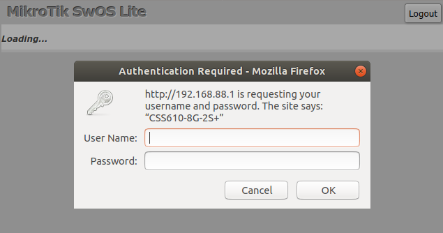
SwOS default IP address: 192.168.88.1, user name: admin and there is no password.
MikroTik Neighbor Discovery can be used to discover the IP address of the Mikrotik switch. LLDP is not supported.
Interface Overview
SwOS interface menu consists of multiple tabs depending on the device model. These are all possible SwOS menus: Link, PoE, SFP, Port Isolation, LAG, Forwarding, RSTP, Stats, Errors, Hist, VLAN, VLANs, Hosts, IGMP, SNMP, ACL, System, Health and Upgrade.
Description of buttons in SwOS configuration tool:
- Append - add a new item to the end of the list
- Apply All - applies current configuration changes
- Cut - removes an item from the list
- Clear - reset properties of the item
- Discard Changes - removes unsaved configuration
- Insert - add a new item to the list (places it before current item)
- Sort - sort VLAN table by VLAN-IDs; sort host table by MAC addresses
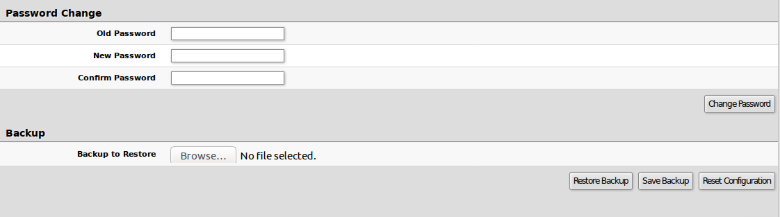
- Change Password - changes the password of the switch
- Logout - logout from the current switch
- Reboot - reboot the switch
- Reset Configuration - reset configuration back to factory defaults
- Choose File - browse for upgrade or backup file
- Upgrade - upgrade the firmware of the switch using the selected file
- Download & Upgrade - automatically try to download and upgrade the firmware, the PC which is running a web browser should be able to access the Internet
- Restore Backup - restore switch using a selected backup file
- Save Backup - generate and download the backup file from the switch
Note: Each RouterBoard switch series device has its own firmware which cannot be installed on other series models!
- CSS610-1Gi-7R-2S+ supports SwOS Lite v2.12 and newer.
- CSS610-8G-2S+ supports SwOS Lite v2.12 and newer.
- CSS610-8P-2S+IN supports SwOS Lite v2.15 and newer.
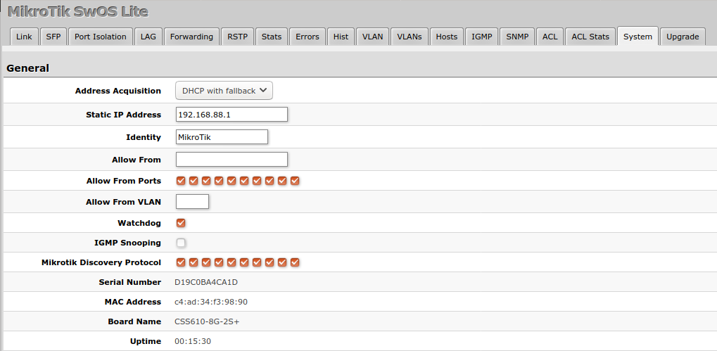
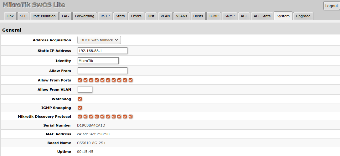
System
System Tab performs the following functions:
- General information about switch
- Switch management
- Configuration reset
- Backup and restore configuration
Note: SwOS uses a simple algorithm to ensure TCP/IP communication - it just replies to the same IP and MAC address packet came from. This way there is no need for Default Gateway on the device itself.
| Property | Description |
|---|---|
| Address Acquisition | Specify which address acquisition method to use:DHCP with fallback - switch is trying to request an IPv4 address from a DHCP server. If the requests are unsuccessful, then the switch can be accessed using a Static IP Address valuestatic - address is set as a Static IP Address value (IPv4 only)DHCP only - switch uses DHCPv4 client to acquire address |
| Static IP Address | IP address of the switch in case of Address Acquisition is set as DHCP with fallback or static |
| Identity | Name of the switch (for Mikrotik Neighbor Discovery protocol) |
| Allow From | IP address from which the switch is accessible. Default value is 0.0.0.0/0 - any address |
| Allow From Ports | List of switch ports from which it is accessible |
| Allow From VLAN | VLAN ID from which the service is accessible. Make sure to first configure VLANs and VLAN pages |
| Watchdog | Enable or disable system Watchdog. It will reset CPU of the switch in case of fault condition |
| IGMP Snooping | Enable or disable IGMP Snooping |
| IGMP Querier | Enables or disables IGMP querier on the switch. Only applies when IGMP Snooping is enabled |
| IGMP Fast Leave | Enables or disables IGMP fast leave feature per switch port |
| IGMP Version | Changes IGMP version for switch querier. Only applies when IGMP Querier is enabled |
| Mikrotik Discovery Protocol | Enable or disable Mikrotik Neighbor Discovery protocol |
| MAC Address | MAC address of the switch (read-only) |
| Serial Number | Serial number of the switch (read-only) |
| Board Name | MikroTik model name of the switch (read-only) |
| Uptime | Current switch uptime (read-only) |
| PoE Out Mode | Specifies PoE-Out state (CSS610-1Gi-7R-2S+ model only):auto-on - the board will attempt to detect if power can be applied to the port. For power-on to happen there should be resistance on spare pairs in the range from 3kΩ to 26.5kΩforced-on - detection range is removed. As a result power over Ethernet will be always onoff - all detection and power is turned off for this port |
| PoE Out Status | Shows current PoE-Out status on port (read-only, CSS610-1Gi-7R-2S+ model only) |
Health

| Property | Description |
|---|---|
| Temperature | Shows CPU temperature in celsius temperature scale (read-only) |
| PSU | Shows PSU voltage and consumed milliamperes by PoE-out connected devices (read-only, CSS610-8P-2S+IN model only) |
| Power Consumption | Shows PSU power consumption by PoE-out connected devices (read-only, CSS610-8P-2S+IN model only) |
DHCP & PPPoE Snooping

| Property | Description |
|---|---|
| Trusted Ports | Group of ports which allows DHCP or PPPoE servers to provide requested information. When enabled, it allows forwarding DHCP client packets towards the DHCP server through this port. Mainly used to limit unauthorized servers from providing malicious information for users; access ports usually are not configured as trusted. Ports that receive DHCP client packets with already added Option-82 must also be trusted, otherwise these packets are dropped. The setting does not apply to DHCPv6 packets. |
| Add Information Option | Enables or disables DHCP Option-82 information. When enabled, the Option-82 information (Agent Remote ID and Circuit ID) is added for DHCP packets received from untrusted ports. Can be used together with an Option-82 capable DHCP server to assign IP addresses and implement policies. The setting does not apply to DHCPv6 packets. For Agent Remote ID, SwOS uses the interface name where DHCP client resides. For Agent Circuit ID, SwOS uses the identity of the SwOS device, internally used port ID and VLAN ID. For example: Agent Remote ID - Port1Agent Circuit ID - MikroTik eth 0/1:100 |
Password and Backup
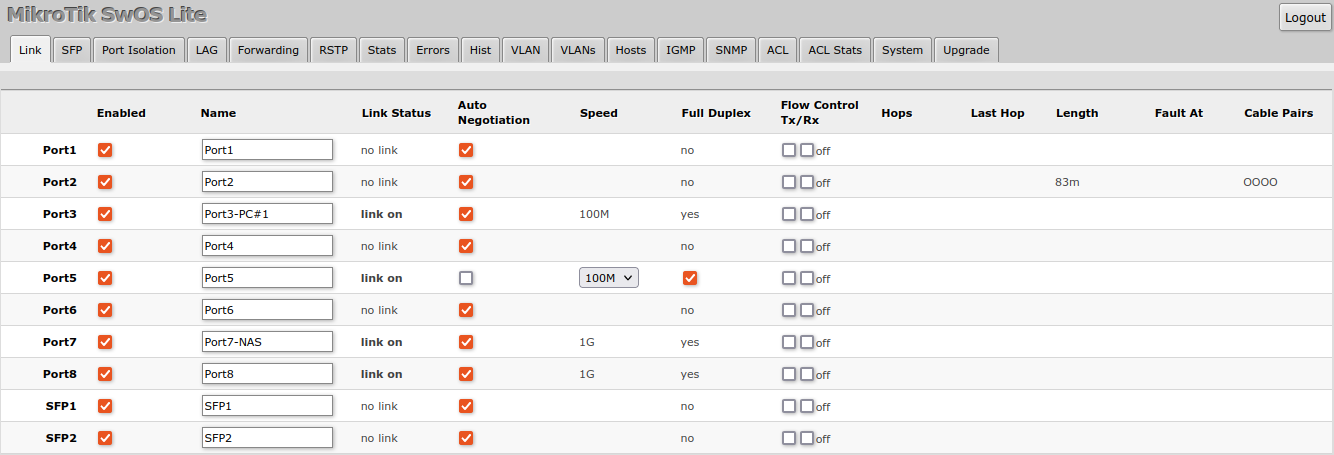
Link
Link Tab allows you to configure each interface settings and monitor the link status.
| Property | Description |
|---|---|
| Enabled | Enable or disable port |
| Name | Editable port name |
| Link Status | Current link status (read-only) |
| Auto Negotiation | Enable or disable auto-negotiation |
| Speed | Specify speed setting of the port (requires auto-negotiation to be disabled) |
| Full Duplex | Specify the duplex mode of the port (requires auto-negotiation to be disabled) |
| Flow control Tx/Rx | Enable or disable 802.3x Flow control |
| Hops | Shows the number of GPER repeaters in the link |
| Last Hop | Shows the number of the last GPER repeater if the link is terminated |
| Length | Shows the length of the cable in meters if the link is terminated |
| Fault At | Shows the distance in meters to the failure point if the cable is damaged but the link is active |
| Cable Pairs | Shows four positions of the cable pairs with their status: O - open; S - short; P - reverse polarity |
The switch supports Jumbo frames up to 10218 bytes. Manually decreasing the MTU settings is not supported for SwOS Lite devices.
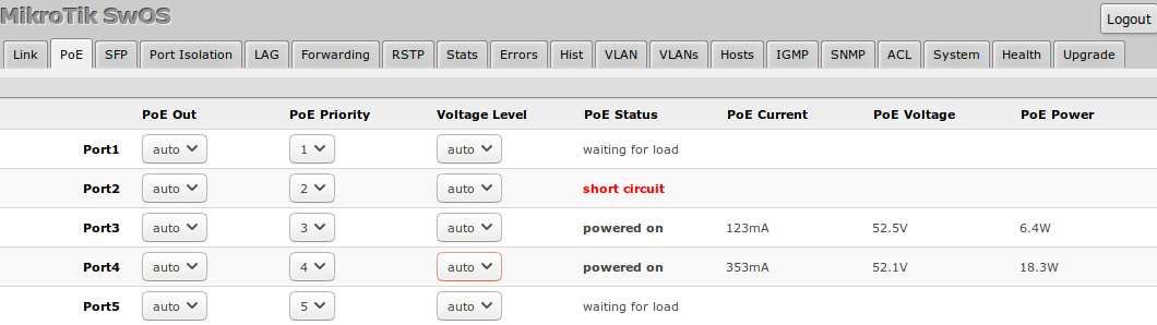
PoE
Devices with PoE-out support have some configuration options and certain monitoring features, like PoE-out current, voltage, etc. For a more detailed description, see PoE-Out manual.
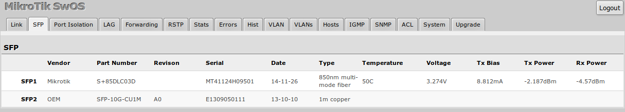
SFP
SFP tab allows you to monitor the status of SFP/SFP+ modules.
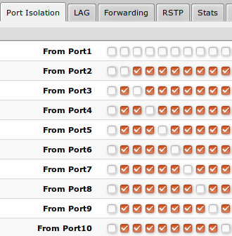
Port Isolation
The Port Isolation table allows or restricts traffic forwarding between specific ports. By default, all available switch chip ports can communicate with any other port — there is no isolation used. When the checkbox is enabled/ticked you allow traffic to forward from this port towards the ticked port. Below are some port isolation examples.
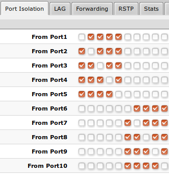
In some scenarios, you might need to isolate a group of devices from other groups. In this example devices on Port1-Port5 are not able to communicate with Port6-Port10 devices, and vice versa.
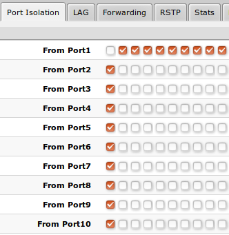
In some scenarios, you might need to forward all traffic to an uplink port while all other ports are isolated from each other. This kind of setup is called a Private VLAN configuration. The switch will forward all Ethernet frames only to the uplink Port1, while the uplink can reach all other ports.
Individual isolated Port1 (e.g. for management purpose) — it cannot send or receive traffic from any other port.
Note: It is possible to check/uncheck multiple checkboxes by checking one of them and then dragging horizontally (Click & Drag).
Note: (R)STP will only work properly in Private VLAN setups. In setups with multiple isolated switch groups, (R)STP might not properly receive BPDUs and therefore fail to detect network loops.
LAG
IEEE 802.3ad (LACP) compatible link aggregation is supported, as well as static link aggregation to ensure failover and load balancing based only on Layer2 hashing. Up to 16 link aggregation groups with up to 8 ports per group are supported. Each individual port can be configured as Passive LACP, Active LACP, or a Static LAG port.
| Property | Description |
|---|---|
| Mode (default: passive) | Specify LACP packet exchange mode or Static LAG mode on ports:Passive - place port in listening state, use LACP only when its contrary port uses active LACP modeActive - prefer to start LACP regardless of contrary port modeStatic - set port in a Static LAG mode; requires setting the same Group setting for all ports that need to be included in the same static LAG |
| Group | Specify a Static LAG group |
| Trunk (read-only) | Represents group number the port belongs to |
| Partner (read-only) | Represents partner MAC address; only available when ports are included in LACP |
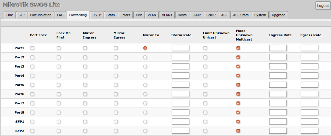
Forwarding
Forwarding Tab provides advanced forwarding options among switch ports, port locking, port mirroring, bandwidth limit, and broadcast storm control features.
| Property | Description |
|---|---|
| Port Lock | Port Lock - Enables or disables MAC address learning on this port. When the option is enabled, it will restrict MAC address learning and static MAC addresses should be configured. Any received frames with unknown source MAC address will be droppedLock On First - Allows learning of the source MAC address from the first received frame; this property should be used together with Port Lock. Learning of the first MAC address will reset every time an interface status changes |
| Port Mirroring | Mirror Ingress - Whether traffic entering this port must be copied and forwarded to the mirroring target portMirror Egress - Whether traffic leaving this port must be copied and forwarded to the mirroring target portMirror To - Mirroring target port |
| Broadcast Storm Control | Storm Rate - Limit the number of broadcast packets transmitted by an interface. The rate is measured in bits per second (bps)Include Unknown Unicast - Include unicast packets without an entry in the host table in Storm Rate limitation |
| Multicast Flood Control | Flood Unknown Multicast - Changes the multicast flood option on a switch port; only controls egress traffic. When enabled, the bridge allows flooding multicast packets to the specified switch port; when disabled, it restricts multicast traffic from being flooded. The setting affects all multicast traffic, including non-IP, IPv4, IPv6 and the link-local multicast ranges (e.g. 224.0.0.0/24 and ff02::1) |
| Bandwidth Limit | Ingress Rate - Limit traffic entering this port (bps)Egress Rate - Limit traffic leaving this port (bps) |
Note: It is possible to limit ingress/egress traffic per port basis. The policer is used for ingress traffic, the shaper is used for egress traffic. The ingress policer controls the received traffic with packet drops — everything that exceeds the defined limit will get dropped. This can affect the TCP congestion control mechanism on end hosts and achieved bandwidth can be actually less than defined. The egress shaper tries to queue packets that exceed the limit instead of dropping them. Eventually, it will also drop packets when the output queue gets full; however, it should allow utilizing the defined throughput better.
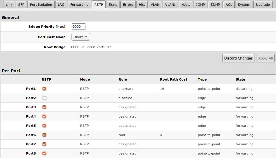
RSTP
Per-port and global RSTP configuration and monitoring are available in the RSTP menu.
| Property | Description |
|---|---|
| Bridge Priority (hex) | RSTP bridge priority for Root Bridge selection |
| Port Cost Mode | There are two methods for automatically detecting RSTP port cost depending on link speed.short: 40G - 1; 10G - 2; 1G - 4; 100M - 10; 10M - 100long: 40G - 500; 10G - 2000; 1G - 20000; 100M - 200000; 10M - 2000000 |
| Forward Reserved Multicast | Whether to forward IEEE reserved multicast MAC address that are in the 01:80:C2:00:00:0x range. Switches compliant with R/M/STP standards should refrain from forwarding these packets. If you enable this setting, SwOS will forward reserved multicast MAC packets and disable RSTP: - the switch will not process incoming BPDUs (Bridge Protocol Data Units) - it will also not send its own BPDUs - Bridge Priority and per-port RSTP configuration settings will no longer have any effect. Enabling forwarding of reserved MAC addresses may affect certain protocols relying on these addresses. It is advisable to enable forwarding only when absolutely necessary, such as in transparent bridging setups (e.g., extending long links, using bridge as media converters, or conducting network analysis). Notable MAC addresses and protocol examples (used by RouterOS): 01:80:C2:00:00:00 - Spanning Tree Protocol (STP)01:80:C2:00:00:01 - Ethernet Flow Control01:80:C2:00:00:02 - Link Aggregation Control Protocol (LACP)01:80:C2:00:00:03 - Dot1x client and server01:80:C2:00:00:08 - Spanning Tree Protocol (for 802.1ad bridges, using ether-type=0x88a8)01:80:C2:00:00:0D - Multiple VLAN Registration Protocol (for 802.1ad bridges, using ether-type=0x88a8)01:80:C2:00:00:0E - Link Layer Discovery Protocol, Multi-chassis Link Aggregation Group and Precision Time ProtocolThe Flow Control MAC address 01:80:C2:00:00:01 is an exception — it does not get forwarded by SwOS. |
| Root Bridge | The priority and MAC address of the selected Root Bridge in the network (read-only) |
| RSTP | Enable or disable STP/RSTP functionality on this port |
| Mode | Shows STP/RSTP functionality mode on a specific port (read-only):RSTPSTP |
| Role | Shows specific port role (read-only):root - port that is facing towards the root bridge and will be used to forward traffic from/to the root bridgealternate - port that is facing towards root bridge, but is not going to forward traffic (a backup for root port)backup - port that is facing away from the root bridge, but is not going to forward traffic (a backup for non-root port)designated - port that is facing away from the root bridge and is going to forward trafficdisabled - port that is not strictly part of STP (RSTP functionality is disabled) |
| Root Path Cost | Shows root path cost for ports that are facing root bridge (read-only) |
| Type | edge - ports that are not supposed to receive any BPDUs, should be connected to the end station (read-only)point-to-point - ports that operate in full-duplex links, can be part of STP and operate in a forwarding state (read-only) |
| State | Shows each port state (read-only):forwarding - port participates in traffic forwarding and is learning MAC addresses, is receiving BPDUsdiscarding - port does not participate in traffic forwarding and is not learning MAC addresses, is receiving BPDUlearning - port does not participate in traffic forwarding but is learning MAC addresses |
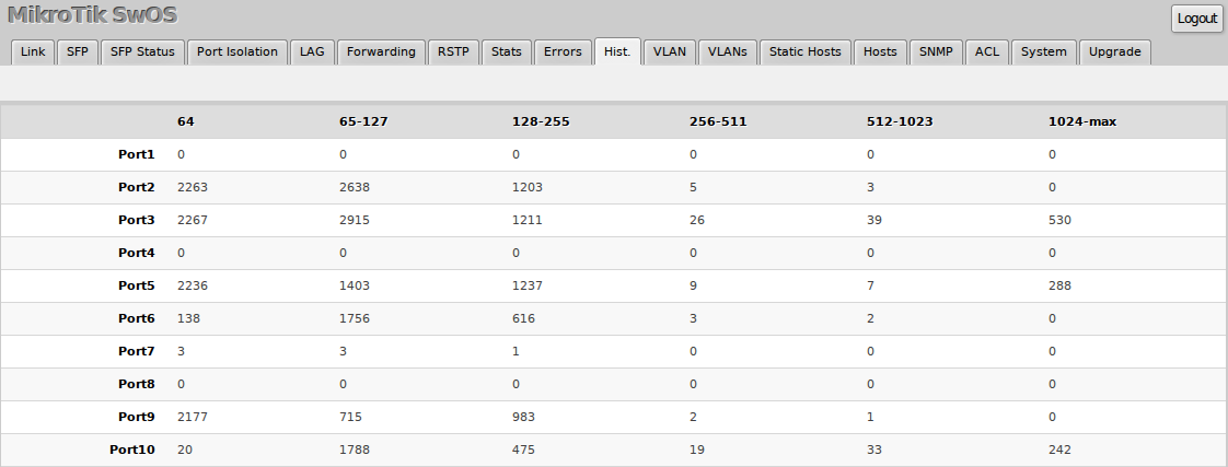
Stats, Errors and Histogram
These menus provide detailed information about received and transmitted packets.
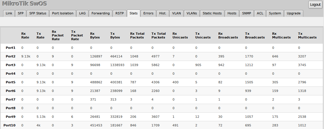
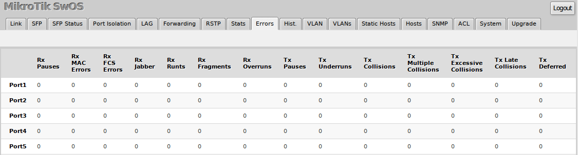
Note: Statistics for SFP+ interface are cleared whenever an active SFP+ link is established.
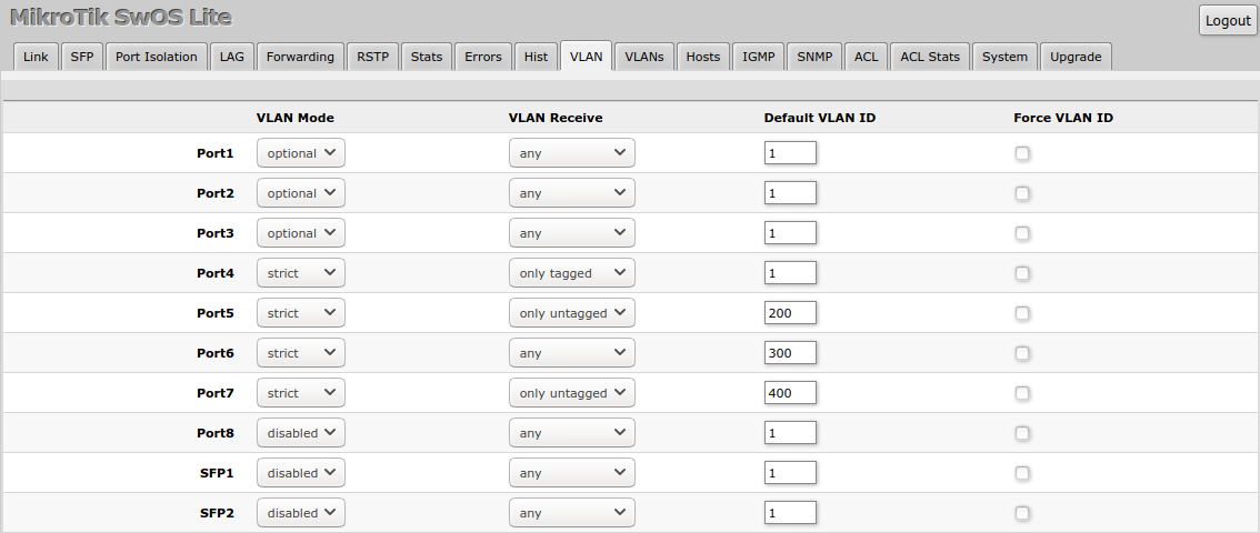
VLAN and VLANs
VLAN configuration for switch ports.
| Property | Description |
|---|---|
| VLAN Mode (disabled | optional | strict; Default: optional) | VLAN filtering mode; these options are relevant to egress ports (except for strict mode).disabled - VLAN table is not used. The switch discards packets with a VLAN tag on egress ports. If the packet has a VLAN tag and the VLAN ID matches Default VLAN ID on egress ports, then with VLAN Receive=any the switch will remove the VLAN tag and forward the packet.optional - Disabled VLAN filtering. Handle packets with VLAN tag ID that is not present in the VLAN table just like packets without VLAN tag.strict - Enabled VLAN filtering with additional ingress filtering, which checks if the ingress port is a member of the received VLAN ID in the VLAN table. Received packets on the ingress port with a VLAN ID that does not match the VLAN table will be dropped. Default VLAN ID must be specified for access ports since it will be used to tag ingress traffic and untag egress traffic for a certain port. |
| VLAN Receive (any | only tagged | only untagged; Default: optional) | Received traffic filtering based on VLAN tag presence.any - allows tagged and untagged packets on a certain portonly tagged - allows only packets with a VLAN tag. The "Default VLAN ID" will not work, because it only applies for untagged trafficonly untagged - allows only packets without a VLAN tag |
| Default VLAN ID (integer: 1..4095; Default: 1) | The switch will place received untagged packets in the "Default VLAN ID" VLAN. Only has an effect on untagged traffic, and when VLAN Receive is set to "any" or "only untagged". It does not apply for tagged traffic. This parameter is usually used to allocate access ports with a specific VLAN. It is also used to untag egress traffic if the packet's VLAN ID matches Default VLAN ID. |
| Force VLAN ID (yes | no; Default: no) | Assigns the Default VLAN ID value to all ingress traffic (tagged and untagged). Has effect in all VLAN Modes. If the port receives tagged traffic and Default VLAN ID is set to 1, then with this parameter the egress traffic will be untagged. |
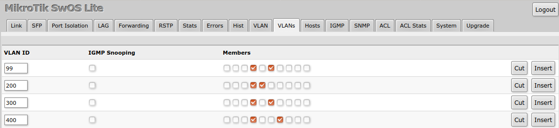
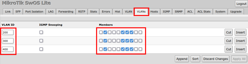
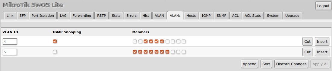
VLAN membership configuration for switch ports.
| Property | Description |
|---|---|
| VLAN ID (integer: 1..4095; Default: 0) | VLAN ID to which assign ports |
| IGMP Snooping (yes | no; Default: no) | Enables or disables IGMP Snooping on the defined VLAN. When enabled, the switch will listen to IGMP Join and Leave requests from the defined VLAN and only forward traffic to ports which have sent IGMP membership requests from the defined VLAN. When disabled, the switch will flood all VLAN member ports with Multicast traffic. |
| Members (ports; Default: none) | Group of ports which are allowed to forward traffic on the defined VLAN |
VLAN Configuration Examples
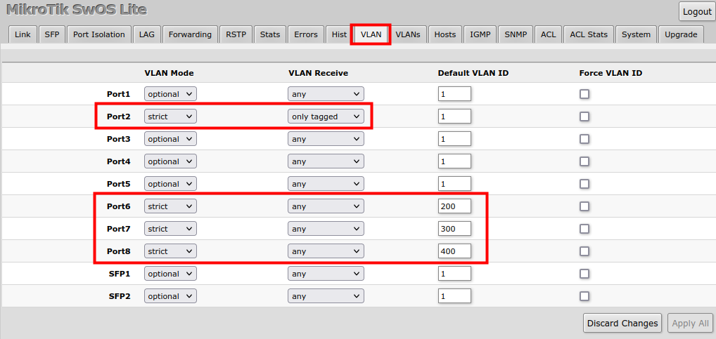
Trunk and Access Ports
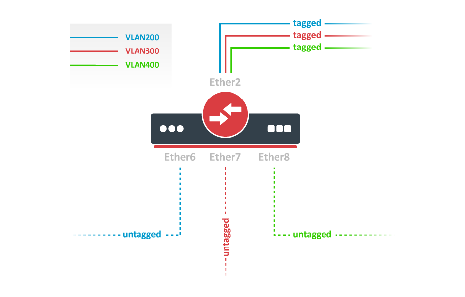
- In the VLANs menu add VLAN entries and specify port membership.
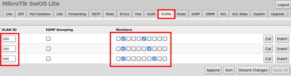
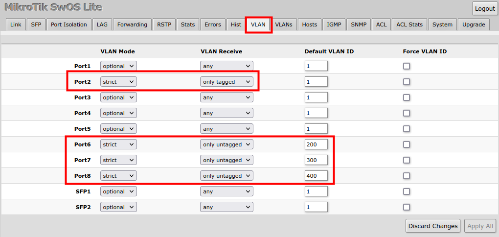
- In the VLAN menu configure Default VLAN ID on planned access ports (untagged), select the correct VLAN Receive setting (Port2 only tagged, Port6-8 only untagged) and enable strict VLAN filtering to ensure only allowed VLANs can pass through the ports.
Trunk and Hybrid Ports
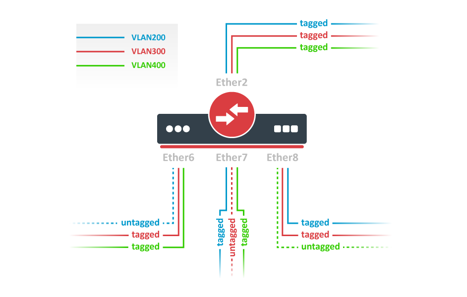
- In the VLANs menu add VLAN entries and specify port membership.
- In the VLAN menu configure Default VLAN ID on planned hybrid ports (for untagged VLAN), select the correct VLAN Receive setting (Port2 only tagged, Port6-8 any) and enable strict VLAN filtering to ensure only allowed VLANs can pass through the ports.
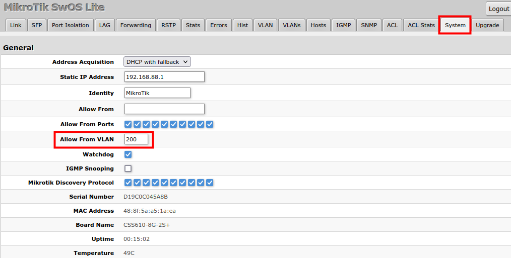
Management Access
In this example, switch management access on VLAN 200 will be created. The configuration scheme is the same as "Trunk and Access Ports" and steps 1., 2. are identical. The additional 3rd step requires specifying the management VLAN ID in the System menu. After applying the configuration, the switch will only respond to tagged VLAN 200 packets on Port2 and untagged packets on Port6. The DHCP client will also work in the specified VLAN ID.
Warning: Changing management VLAN can completely disable access to the switch management if VLAN settings are not correctly configured. Save a configuration backup before changing this setting and use Reset and Reinstall in case management access is lost.
Hosts
This table represents dynamically learned MAC address to port mapping entries. It can contain two kinds of entries: dynamic and static. Dynamic entries get added automatically — this is also called a learning process: when a switch receives a packet from a certain port, it adds the packet's source MAC address and port it received the packet from to the host table, so when a packet comes in with a certain destination MAC address it knows to which port it should forward the packet. If the destination MAC address is not present in the host table then it forwards the packet to all ports in the group. Dynamic entries take about 5 minutes to time out.
Static entries will take over dynamic entries if a dynamic entry with the same MAC address already exists. Adding a static entry also provides access to more functionality.
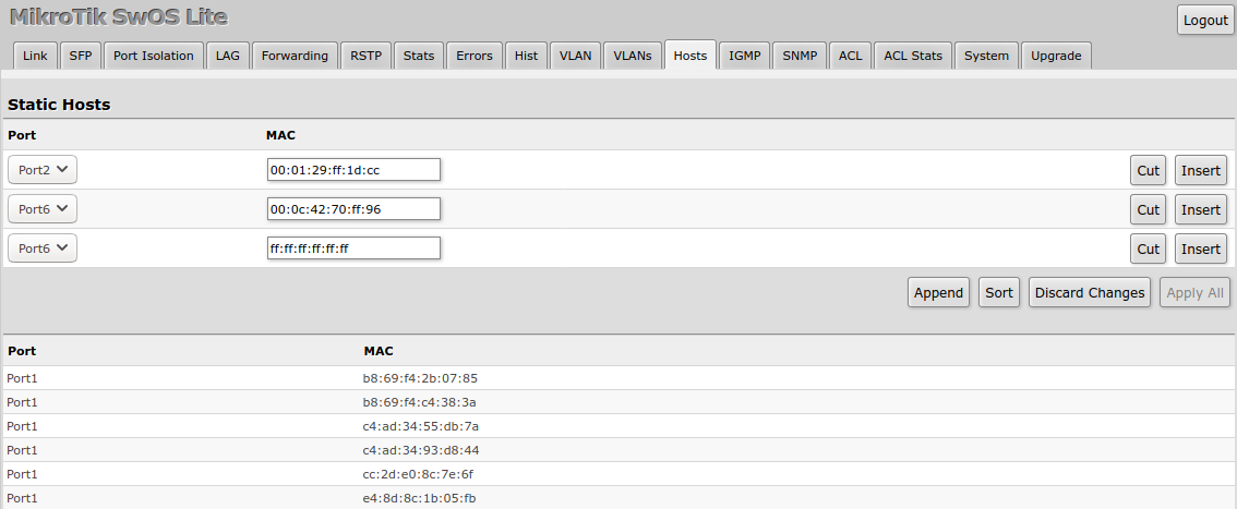
Static host properties
| Property | Description |
|---|---|
| Ports | Ports the packet should be forwarded to |
| MAC | MAC address |
Dynamic host properties (read-only)
| Property | Description |
|---|---|
| Port | Ports the packet should be forwarded to |
| MAC | Learned MAC address |
IGMP Snooping
IGMP Snooping controls multicast streams and prevents multicast flooding. The feature allows a switch to listen in the IGMP conversation between hosts and routers.
Enable this option under the System tab.
Available IGMP snooping data can be found under the IGMP tab.
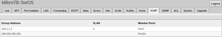
It is possible to enable IGMP Snooping for a specific VLAN ID under the VLANs menu.
SNMP
SwOS supports SNMP v1 and v2c (the Response for GetRequest, GetNextRequest and GetBulkRequest) and uses IF-MIB, SNMPv2-MIB, BRIDGE-MIB and MIKROTIK-MIB (only for health, PoE-out and SFP diagnostics). SNMP traps and writing SwOS configuration are not supported.
Available SNMP data:
- System information
- System uptime
- Port status
- Interface statistics
- Host table information

| Property | Description |
|---|---|
| Enabled | Enable or disable SNMP service |
| Community | SNMP community name |
| Contact Info | Contact information for the NMS |
| Location | Location information for the NMS |
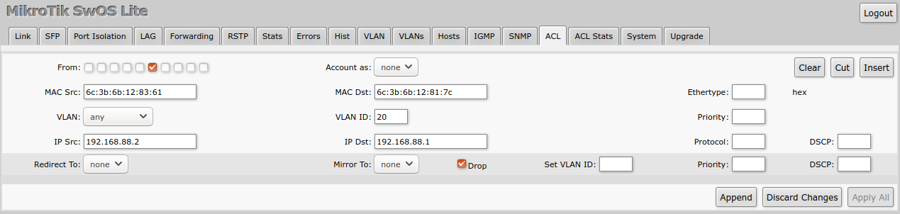
ACL and ACL Stats Tabs
An access control list (ACL) rule table is a very powerful tool allowing wire-speed packet filtering, forwarding, and VLAN tagging based on L2, L3, and L4 protocol header field conditions. Each rule contains a conditions part and an action part.
Conditions part parameters
| Property | Description |
|---|---|
| From | A port that the packet came in from |
| MAC Src | Source MAC address and mask |
| MAC Dst | Destination MAC address and mask |
| Ethertype | Protocol encapsulated in the payload of an Ethernet Frame |
| VLAN | VLAN header presence: any / present / not present |
| VLAN ID | VLAN tag ID |
| Priority | Priority in VLAN tag |
| IP Src (IP/netmask:port) | Source IPv4 address, netmask, and L4 port number |
| IP Dst (IP/netmask:port) | Destination IPv4 address, netmask, and L4 port number |
| Protocol (integer) | IP protocol |
| DSCP | IP DSCP field |
Action part parameters
| Property | Description |
|---|---|
| Account as | Select the counter where matched packets will be counted |
| Redirect To | Force new packets destination port |
| Mirror | Clones packet and sends it to mirror-target port |
| Drop | Drop packet |
| Set VLAN ID | Changes the VLAN tag ID, if VLAN tag is present |
| Priority | Changes the VLAN tag priority bits, if VLAN tag is present |
| DSCP | Changes the IP DSCP field |
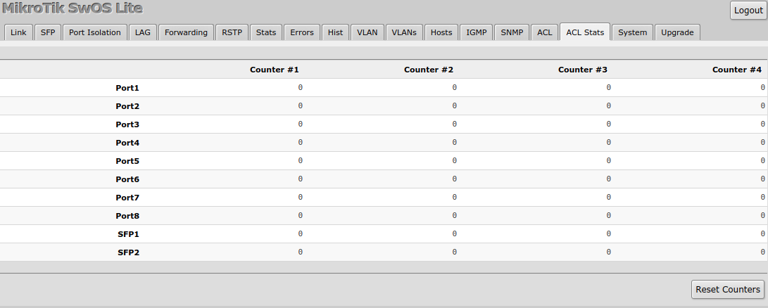
Each ACL rule can be assigned to a specific counter where matched packets will be counted.
Reset and Reinstall
The CSS610 have built-in backup SwOS firmware which can be loaded in case standard firmware breaks or upgrade fails:
- Holding the Reset button for a few seconds while the device is booting will reset the configuration and load backup firmware.
- After loading backup firmware, it is possible to connect to 192.168.88.1 (or a leased address from a DHCP server) using a web browser and install new SwOS firmware.