Serial Console
The Serial Console and Serial Terminal are tools used to communicate with devices and other systems that are interconnected via the serial port. The serial terminal may be used to monitor and configure many devices - including modems, network devices (including MikroTik routers), and any device that can be connected to a serial (asynchronous) port.
The Serial Console feature is for configuring direct-access configuration facilities (monitor/keyboard and serial port) that are mostly used for initial or recovery configuration. A special null-modem cable is needed to connect two hosts (like two PCs, or two routers; not modems). Note that a terminal emulation program (e.g., HyperTerminal on Windows or minicom on Linux) is required to access the serial console from another computer. Default settings of the router's serial port are 115200 bits/s (for x86 the default is 9600 bits/s), 8 data bits, 1 stop bit, no parity, hardware (RTS/CTS) flow control.
Several customers have described situations where the Serial Terminal (managing side) feature would be useful:
- On a mountaintop, where a MikroTik wireless installation sits next to equipment (including switches and Cisco routers) that can not be managed in-band (by telnet through an IP network).
- Monitoring weather-reporting equipment through a serial port.
- Connection to a high-speed microwave modem that needs to be monitored and managed by a serial connection.
With the serial-terminal feature of the MikroTik, up to 132 (and, maybe, even more) devices can be monitored and controlled.
Serial Console Connections
Serial communications between devices are done with RS232. It is one of the oldest and most widespread communication methods in the computer world. It was used for communication with the modems or other peripheral devices DTE/DCE. In the modern world, the main use of serial communication is DTE/DTE communication (Data Terminal Equipment) e.g. using a null-modem cable. There are several types of null modem cables and some of them may not work with RouterBoards at all.
Null Modem Without Handshake
This cable does not utilize handshake pins at all:
| Side1 (DB9f) | Side2 (DB9f) | Function |
|---|---|---|
| 2 | 3 | Rx ← Tx |
| 3 | 2 | Tx → Rx |
| 5 | 5 | GND |
It allows data-only traffic on the cross-connected Rx/Tx lines. Hardware flow control is not possible with this type of cable. The only way to perform flow control is with software flow control using the XOFF and XON characters.
Null Modem With Loopback Handshake
The problem with the first cable is that when connected to a device on which hardware flow control is enabled, software may hang when checking modem signal lines.
A Null modem cable with loopback handshake fixes the problem; its main purpose is to fool well-defined software into thinking there is handshaking available:
| Side1 (DB9f) | Side2 (DB9f) | Function |
|---|---|---|
| 2 | 3 | Rx ← Tx |
| 3 | 2 | Tx → Rx |
| 5 | 5 | GND |
| 1+4+6 | - | DTR → CD + DSR |
| - | 1+4+6 | DTR → CD + DSR |
| 7+8 | - | RTS → CTS |
| - | 7+8 | RTS → CTS |
Hardware flow control is not possible with this cable. Also, if remote software does not send its own ready signal to DTR output, communication will hang.
Null Modem With Partial Handshake
This cable can be used when flow control is enabled without being incompatible with the original way flow control was used with DTE/DCE communication.
This type of cable is not recommended for use with RouterOS.
| Side1 (DB9f) | Side2 (DB9f) | Function |
|---|---|---|
| 1 | 7+8 | RTS2 → CTS2 + CD1 |
| 2 | 3 | Rx ← Tx |
| 3 | 2 | Tx → Rx |
| 4 | 6 | DTR → DSR |
| 5 | 5 | GND |
| 6 | 4 | DSR ← DTR |
| 7+8 | 1 | RTS1 → CTS1 + CD2 |
Null Modem With Full Handshake
Used with special software and should not be used with RouterOS.
| Side1 (DB9f) | Side2 (DB9f) | Function |
|---|---|---|
| 2 | 3 | Rx ← Tx |
| 3 | 2 | Tx → Rx |
| 4 | 6 | DTR → DSR |
| 5 | 5 | GND |
| 6 | 4 | DSR ← DTR |
| 7 | 8 | RTS → CTS |
| 8 | 7 | CTS ← RTS |
Null Modem Compatibility
Summary tables below will allow you to choose the proper cable for your application.
| No handshake | Loopback handshake | Partial handshake | Full handshake | |
|---|---|---|---|---|
| RouterBoards with limited port functionality | Y | Y | N* | N |
| RouterBoards with full functionality | Y | Y | Y | N |
* - may work only when hardware flow control is disabled
| No handshake | Loopback handshake | Partial handshake | Full handshake | |
|---|---|---|---|---|
| Software flow control only | Y | Y* | Y** | Y** |
| Low-speed DTE/DCE compatible hardware flow control | N | Y | Y* | N |
| High-speed DTE/DCE compatible hardware flow control | N | Y | Y** | N |
| High-speed communication using special software | N | N | Y* | Y |
* - will work as an alternative
** - will work but is not recommended
RJ45 Type Serial Port
This type of port is used on RouterBOARD 2011, 3011, 4011, CCR1072, CCR1036 r2, CCR2xxx and CRS series devices, sometimes called "Cisco style" serial port.
RJ45 to DB9 Cable Pinout:
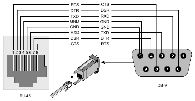
| Signal | Console Port (DTE) RJ-45 | RJ-45 Rolled Cable RJ-45 Pin | Adapter DB-9 Pin | Adapter DB-25 Pin | Signal |
|---|---|---|---|---|---|
| RTS | 1 | 8 | 8 | 5 | CTS |
| DTR | 2 | 7 | 6 | 6 | DSR |
| TxD | 3 | 6 | 2 | 3 | RxD |
| Ground | 4 | 5 | 5 | 7 | Ground |
| Ground | 5 | 4 | 5 | 7 | Ground |
| RxD | 6 | 3 | 3 | 2 | TxD |
| DSR | 7 | 2 | 4 | 20 | DTR |
| CTS | 8 | 1 | 7 | 4 | RTS |
RB M33G Additional Serial Header
For the RBM33G an additional serial header can be attached to GPIO pins U3_RXD, GND, U3_TXD, and 3V3
CCR Serial Header
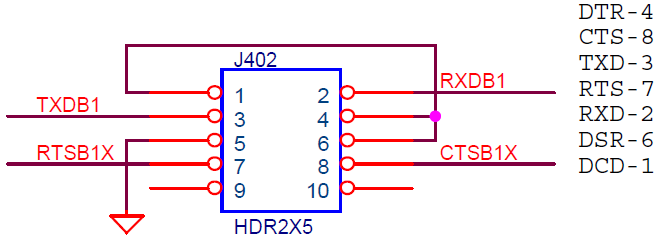
The Cloud Core Router series devices have a serial header on the PCB board, called J402 or 100
Here is the pin-out of that connector:
Serial Terminal Usage
RouterOS allows communication with devices and other systems that are connected to the router via the serial port using a /system/serial-terminal command. All keyboard input will be forwarded to the serial port and all data from the port is output to the connected device.
First, you have to have a free serial port. If the device has only one serial port (like all RouterBoards, WRAP/ALIX boards, etc.), you will have to disable the system console on this serial port to be able to use it as Serial Terminal for connection to other equipment (switches, modems, etc):
/system/console/disable 0
Be sure to just disable the console rather than removing it, as RouterOS will recreate the console after the next reboot when you actually remove it.
Note that there are some caveats you should be aware of! Take your time understanding those limits to avoid strange things happening when connecting a device to a serial port on a RouterBoard:
-
By re-configuring port Serial0 on a RouterBoard as seen above, you will lose your serial console access to RouterOS. This means, that if you cannot access your RouterBoard over the network anymore, you might even have to reset the whole configuration of it to gain access again.
-
When rebooting a RouterBoard, the boot loader (RouterBOOT) will always use the serial console (Serial0 on RouterBoards) to send out some startup messages and offer access to the RouterBOOT menu.
Having text coming out of the serial port to the connected device might confuse your attached device. Furthermore, in the standard config, you can enter the RouterBOOT menu by pressing ANY key. So if your serial device sends any character to the serial port of your RouterBoard during boot time, the RouterBoard will enter the RouterBOOT menu and will NOT boot RouterOS unless you manually intervene!
You can reconfigure RouterBOOT to enter the RouterBOOT menu only when a Delete character is received - use this to reduce the chance of getting a router that's stuck when rebooting!
Or, if newer versions are used, the "Silent boot" feature can be used to suppress any output on the serial interface, including the removal of booting sounds.
Next, you will have to configure your serial port according to the serial port settings of the connected device. Using the following command you will set your serial port to 19200 Baud 8N1. What settings you need to use depends on the device you connect to:
/port/set serial0 baud-rate=19200 data-bits=8 parity=none stop-bits=1
You can also try to let RouterOS guess the needed baud rate by setting
/port/set serial0 baud-rate=auto
Now's the time to connect your device if not already done. Usually, you will have to use a null modem cable (the same thing as a cross-over-cable for Ethernet). Now we're ready to go:
/system/serial-terminal serial0
This will give you access to the device you connected to port Serial0. Control+A is the prefix key, which means that you will enter a small "menu". If you need to send the Control+A character to a remote device, press Control+A twice.
If you want to exit the connection to the serial device, type Control+A, then Q. This will return you to your RouterOS console.
Do not connect to devices at an incorrect speed and avoid dumping binary data.
Special Login
Special login can be used to access another device (like a switch, for example) that is connected through a serial cable by opening a telnet/ssh session that will get you directly to this device (without having to log in to RouterOS first).
For this demonstration we will use two RouterBoards and one PC.
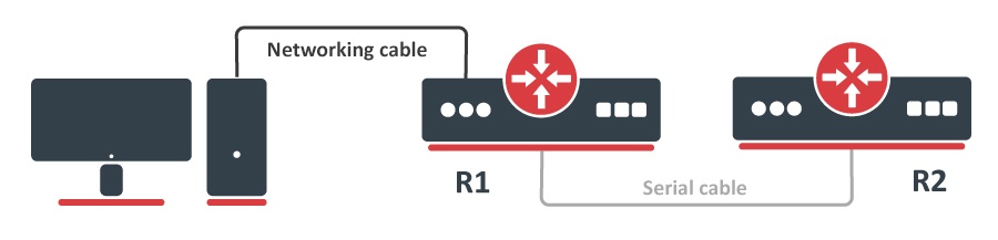
Routers R1 and R2 are connected with a serial cable and a PC is connected to R1 via ethernet. Let's say we want to access router R2 via serial cable from our PC. To do this you have to set up a serial interface proxy on R1. It can be done by a feature called special-login.
By default console is bound to serial port.
The first task is to unbind console from serial simply by disabling the entry in /system/console menu:
[admin@MikroTik] /system/console> print
Flags: X - disabled, U - used, F - free
 #   PORT                                                                    TERM
 0 X serial0                                                                 vt102
Next step is to add a new user, in this case serial, and bind it to the serial port
[admin@MikroTik] > /user/add name=serial group=full
[admin@MikroTik] > /special-login/add user=serial port=serial0 disabled=no
[admin@MikroTik] > /special-login/print
Flags: X - disabled
 #   USER                                                                    PORT
 0   serial                                                                  serial0
Now we are ready to access R2 from our PC.
maris@bumba:/$ ssh serial@10.1.101.146

[Ctrl-A is the prefix key]
R2 4.0beta4
R2 Login:

[admin@R2] >
To exit the special login mode, press Ctrl+A and Q
[admin@MikroTik] >
[Q - quit ] [B - send break]
[A - send Ctrl-A prefix] [R - autoconfigure rate]
Connection to 10.1.101.146 closed.
After router reboot and serial cable attached router may be stuck at the Bootloader main menu
To fix this problem you need to allow access to the bootloader main menu from <any> key to <delete>:
- Enter bootloader menu.
- Press 'k' for boot key options.
- Press '2' to change key to
<delete>.
What do you want to configure?
d - boot delay
k - boot key
s - serial console
n - silent boot
o - boot device
u - cpu mode
f - cpu frequency
r - reset booter configuration
e - format nand
g - upgrade firmware
i - board info
p - boot protocol
b - booter options
t - call debug code
l - erase license
x - exit setup
your choice: k - boot key

Select key which will enter setup on boot:
 * 1 - any key
   2 - <Delete> key only

your choice: 2