PoE-Out
Summary
This page explains using the PoE-Out (Power over Ethernet) feature available on MikroTik devices equipped with at least one PoE-Out interface. MikroTik devices utilize an RJ45 mode B pinout for power delivery, with PoE supplied through pins 4 and 5 (+) and pins 7 and 8 (-).
When powering other devices via PoE-Out, it is recommended to use a minimum input voltage of 18V, unless the device supports multiple output voltages (e.g., CRS112-8P-4S-IN, CRS328-24P-4S+RM, CRS354-48P-4S+2Q+RM).
MikroTik supported PoE-Out standards
MikroTik devices can support some or all of the following PoE standards:
-
Passive PoE-Out up to 30 V - PoE standard, which does not require negotiation between PSE (Power Sourcing Equipment) and PD (Powered Device). PoE-out uses the same voltage as supplied to the PSE (Power Sourcing Equipment). PoE-Out Standard for devices that support input voltage up to 30 V. (e.g. hEX PoE lite, RB3011UiAS-RM, RB2011iL-IN.)
-
Passive PoE-Out up to 57 V - Works the same as low voltage (up to 30 V) PoE-Out, but is also capable of delivering high voltage over PoE ports. The output voltage depends on the power source connected to the PSE. Can power up af/at compatible devices, which accept power over 4,5 (+) and 7,8 (-), and do not require PoE negotiation. (e.g. cAP ac, hAP ac, wsAP ac lite.)
-
IEEE Standards 802.3af/at - Also known as PoE+ Type 1 (af) and PoE+ Type 2 (at), these IEEE standards aim to ensure compatibility between vendors. MikroTik PSEs that support these standards can power both Type 1 and Type 2 PDs. MikroTik devices that support af/at standard can also power devices that accept Passive PoE-In. (e.g. CRS112-8P-4S-IN, CRS328-24P-4S+RM, CRS354-48P-4S+2Q+RM.)
-
IEEE Standards 802.3bt- The 802.3bt standard, also known as PoE++, extends the earlier PoE standards and introduces "Type 3" (Classes 5-6) and "Type 4" (Classes 7-8). This standard uses all four pairs of wires in Gigabit Ethernet cable to deliver power, hence the name of the standard - 4PPoE/802.3bt ("4-pair Power over Ethernet"). 802.3bt powering is isolated from PoE-Out and the device powering itself. (e.g. CRS320-8P-8B-4S+RM)
Each PoE-Out implementation supports overload and short-circuit detection.
If the specification page of the device indicates that it is able to provide Low voltage PoE-Out current limit, under the "PoE-OUT" section, it means the device supports Passive PoE-Out up to 30 V. If it also indicates High voltage PoE-Out current limit, it means the device also supports Passive PoE-Out up to 57.
As per the above section, Passive PoE-Out up to 57 is also able to power af/at compatible devices, which do not require PoE negotiation. For MikroTik PDs, it should work with no issues. However, a 3rd-party PD can assign a lower PoE class to itself as a result of no-negotiation, which can result in less power requested by the PD (which in turn, for example, can result in PD's lower radio output power, disabled peripherals etc.). Different PDs can behave differently.
How to choose your PoE PSE
This table can help you choose which PSE device is best suitable for your needs.
| Device name | PoE-Out port count | Passive PoE | 802.3af/at | 802.3bt | Power input | Maximum output per port | Maximum power output, W | |
|---|---|---|---|---|---|---|---|---|
| Input 18-30V, mA | Input 30-57V, mA | |||||||
| CSS610-8P-2S+IN | 8 | + | + | - | AC &DC 48-57 V | 1000 | 625 | 140 |
| CRS328-24P-4S+RM | 24 | + | + | - | AC | 1000 | 450 | 450 |
| CRS354-48P-4S+2Q+RM | 48 | + | + | - | AC | 1000 | 570 | 700 |
| CRS112-8P-4S-IN | 8 | + | + | - | DC 18-30V & DC 30-57V | 1000 | 450 | 150 |
| netPower 16P | 16 | + | + | - | DC 18-30V & DC 30-57V | 1100 | 600 | 160 |
| RB5009UPr+S+ | 8 | + | + | - | DC 18-30V or DC 30-57V | 900 | 440 | 130 |
| hEX PoE | 4 | + | + | - | DC 18-30V or DC 30-57V | 1000 | 450 | 102 |
| PowerBox Pro | 4 | + | + | - | DC 18-30V or DC 30-57V | 1000 | 450 | 102 |
| OmniTIK 5 PoE ac | 4 | + | + | - | DC 18-30V or DC 30-57V | 1000 | 450 | 102 |
| hEX PoE lite | 4 | + | - | - | DC 18-30V | 1000 | - | 60 |
| PowerBox | 4 | + | - | - | DC 18-30V | 1000 | 60 | |
| RB260GSP | 4 | + | - | - | DC 18-30V | 1000 | 60 | |
| OmniTIK 5 PoE | 4 | + | - | - | DC 18-30V | 1000 | 60 | |
| CRS320-8P-8B-4S+RM | 16 | + | + | + | AC | - | 560 (af/at) / 1667 (bt) | 963 |
PoE-Out Configuration
PoE Configuration is supported on all MikroTik devices with PoE-Out interfaces. The configurations can be edited from the RouterOS and SwOS interfaces.
RouterOS
Sub-menu: /interface/ethernet/poe
Usage
RouterOS provides an option to configure PoE-Out over Winbox, Webfig, and CLI. Basic commands using the CLI are
| Property | Description |
|---|---|
| print () | Prints PoE-Out related settings. |
| export () | Export is displayed under the /interface/ethernet menu. |
| monitor (string| interface) | Shows poe-out-status of a specified port, or all ports with /interface/ethernet/poe/monitor [find] command. |
| power-cycle (duration:0..1m |; Default: 5s) | Disables PoE-Out power for a specified period of time. |
Global Settings
Sub-menu: /interface/ethernet/poe/settings
Some MikroTik PoE-Out devices support the global PoE settings
| Property | Description |
|---|---|
| ether1-poe-in-long-cable (yes | no) | Setting it to "yes" will disable short detection on all poe-out ports. This is a potentially dangerous setting and should be used with caution. This feature disables strict input/output current monitoring (short detection) to allow the use of PoE-Out with long ethernet cables and/or avoiding improper short-circuit detection. It can also affect PoE-Out behavior on a PSE which is powered using a DC connector |
| psuX-max-power | Specifies the maximum power in watts that the PSU can draw. default - 96W psu1 - RB5009UPr+S+IN = DC-jack |
| routerboard-max-self-power | Specifies how much power the device reserves for itself for powering. |
| poe-out-limit-power | PoE-Out budget limit |
| psuX-poe-out-max-power | PoE-Out limit in watts per PSU |
Port Settings
PoE-Out can be configured under the menu. Each port can be controlled independently.
| Property | Description |
|---|---|
| name () | Name of an interface |
| poe-out (auto-on | forced-on | off; Default: auto-on) | Specifies PoE-Out state
Important: Note: Short-circuit and overload protection is always on independently of the selected PoE-Out state. |
| poe-priority (integer:0..99 | any; Default: 10) | poe-priority specifies the importance of PoE-Out ports, in cases when a total PoE-Out limit is reached, the interface with the lowest port priority will be powered off first. Highest priority is 0, the lowest priority is 99. If there are 2 or more ports with the same priority then the port with the smallest port number will have a higher priority. Every 6 seconds ports will be checked for a possibility to provide PoE-Out if it was turned off due to port priority. |
| poe-voltage (auto | low | high; Default: auto) | A feature that allows us to manually switch between two voltage outputs on PoE-Out ports. It will take effect only on PSEs with switchable voltage modes (CRS112-8P-4S-IN, CRS328-24P-4S+RM, netPower 16P, CRS354-48P-4S+2Q+RM). |
| poe-lldp-enabled*( yes / no;* Default: no) | Link Layer Discovery Protocol (LLDP) is a layer-2 Ethernet protocol for managing devices. LLDP allows an exchange of information between a PSE and a PD. Starting from RouterOS version 7.15, the setting has been replaced with the Neighbor Discovery lldp-poe-power property. |
Power-cycle settings
RouterOS provides a possibility to monitor PD using a ping, and power-cycle a PoE-Out port when the host does not respond. The power-cycle-ping feature can be enabled under the /interface/ethernet/poe menu.
| Property | Description |
|---|---|
| power-cycle-ping-enabled (yes | no; Default: no) | Enables ping watchdog, power-cycles port if a host does not respond to ICMP or MAC-Telnet packets. |
| power-cycle-ping-address (IPv4 | IPv6 | MAC; Default: ) | An address which will be monitored. Since RouterOS 6.46beta16, an active route towards PD is required in case an IP address is configured, so make sure PSE can reach the PD. In case the MAC address is specified, PSE will send MAC-Telnet ping requests only from a specified ethernet interface. When configuring a bridge vlan-filtering or some way of VLAN switching, it is recommended to use the IP address for monitoring your PD. |
| power-cycle-ping-timeout (time:0..1h |; Default: 5s) | If the host does not respond for more than the timeout period of time, then PoE-Out port is switched off for 5s. |
| power-cycle-interval (time| any; Default: ) | Disables PoE-Out power for 5s between the specified intervals. Not related to the power-cycle-ping feature. |
If power-cycle is enabled, /interface/ethernet/poe/monitor will show the actual status of the host and the time when the power cycle will be performed PoE-Out Monitoring.
power-cycle-host-alive: YES/NO (Shows if the monitored host is reachable) power-cycle-after: TIME (Shows the time, after which the port will be power-cycled)
SwOS
SwOS interface provides basic PoE-Out configuration and monitoring options, see more details in the SwOS PoE user manual.
PoE-Out Monitoring
RouterOS
Sub-menu: /interface/ethernet/poe/monitor
| Property | Description |
|---|---|
| name () | Name of an interface |
| poe-out () | Shows PoE-Out state |
| poe-out-status () | Shows the current PoE-Out status on the port
PD uses a second power source which has a higher voltage than PSE, so all current is taken from the second DC source, not the PSE PoE-Out port.
|
| poe-out-voltage () | Displays PoE Voltage which is applied to the PD. |
| poe-out-current () | Displays the port current (mA) which is drawn by the PD. |
| poe-out-power () | Displays PD power consumption |
| poe-out-power-pair() | Displays on which power pair PSE is delivering power to PD. (a = 1,2(+) 3,6(-) ; b = 4,5(+) 7,8(-) ; bt = all 4 pairs). |
If the power-cycle-ping feature is used, /interface/ethernet/poe/monitor [find] will show additional fields:
SNMP
It is possible to monitor PoE-Out values using the SNMP protocol. This requires enabled SNMP on PSE.
SNMP OID tables:
- 1.3.6.1.4.1.14988.1.1.15.1.1.1 - interface-id
- 1.3.6.1.4.1.14988.1.1.15.1.1.2 - interface names
- 1.3.6.1.4.1.14988.1.1.15.1.1.4 - voltage in dV (decivolt)
- 1.3.6.1.4.1.14988.1.1.15.1.1.5 - current in mA
- 1.3.6.1.4.1.14988.1.1.15.1.1.6 - power usage in dW (deciwatt)
SNMP values can be also requested from RouterOS, for example, snmp-walk will print current mA from all available PoE-Out ports:
/tool/snmp-walk address=10.155.149.252 oid=1.3.6.1.4.1.14988.1.1.15.1.1.5
To get a very specific OID value, use the snmp-get tool (displays current mA on ether3 interface):
tool snmp-get address=10.155.149.252 oid=1.3.6.1.4.1.14988.1.1.15.1.1.5.3
PoE-Out notifications
PoE-Out LEDs
Models with dependant voltage output
PoE-Out LED behavior can differ between models, but most of them will indicate PoE-Out state on one additional LED. Devices with one voltage output will light:
- Red color LED - PoE-Out port state is powered-on (auto or forced-on mode).
- Blinking Red color LED - PoE-Out port state is short-circuit.
Models with selectable voltage output
Models with multiple voltage options can indicate additional information:
- Green color triangle LED - PoE-Out port state is powered-on, PD uses low voltage.
- Red color triangle LED - PoE-Out port state is powered-on, PD uses high voltage.
- Blinking Green color LED - PoE-Out port state for low voltage is short-circuit or overload.
- Blinking Red color LED - PoE-Out port state for high voltage is short-circuit or overload.
Model-specific LED behavior
- CRS112-8P-4S-IN, netPower 16P - All PoE LEDs flashing: wrong voltage PSU plugged into one of the ports.
- CRS320-8P-8B-4S+RM - Purple color LED - PoE-Out port state is powered-on, PD uses high voltage (802.3bt). Blinking Purple color triangle LED - PoE-Out port state is a short-circuit or an overload.
PoE-Out Logs
By default, PoE-Out event logging is enabled and uses "warning" and "info" topics to notify the user about PoE-Out state changes. Log entries will be added to each PoE-Out state change. Important logs will be added with a "warning" topic, informative logs will be added with the "info" topic. When PoE LLDP is enabled, LLDP status updates are available in the device logs, for example:
06:56:50 poe-out,debug ether4 LLDP TLV 25.0W request denied : hw-limit
Possible denial reasons:
- budget - requested power exceeds the total PSE budget.
- hw-limit - requested power is more than hardware supports (PSU affects this).
- low-voltage - LLDP request made to a low-voltage port.
- off - the port is shut down.
- class-limit - LLDP requires more than the class can provide.
- cmd-failed - RouterOS could not make a request to the controller.
To avoid unnecessary logging in cases when PD is not powered because of current-too-low, RouterOS will filter such events, and add one log per 512 current-too-low events.
Logs can be disabled if necessary:
/system/logging/set [find topics~"info"] topics=info,!poe-out
/system/logging/set [find topics~"warning"] topics=warning,!poe-out
PoE-Out Warnings in GUI/CLI
To notify a user about important PoE-Out related problems, messages will be shown in Winbox / WebFig and CLI interface fields:
1 RS ;;; poe-out status: overload
ether1 ether 1500 1588 9204 64:D1:54:61:D5:E0
WebFig and Winbox will notify the user under interfaces:
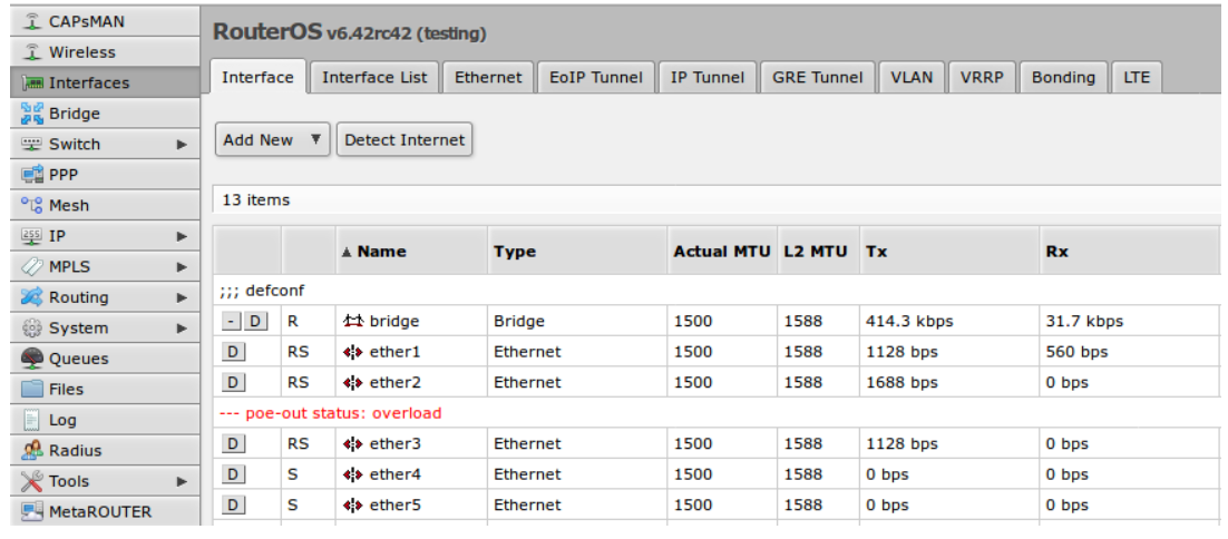
How it works
PoE-Out Modes
auto-on mode
If auto-on is selected on the PoE-Out interface, then the port operates in this strict order:
- PSE with low voltage checks for resistance on the connected port. If the detected resistance range is between (3kΩ and 26.5kΩ) power is turned on.
- When power is applied, the PSE continuously checks if the overload limit is not reached or a short circuit is detected.
- If the cable is unplugged, the port returns to the detection state and will remain off until a suitable PD is detected.
forced-on mode
If forced-on is selected then port operates in this strict order:
- PSE disables resistance check on the port, and applies power on pins depending on the poe-out() state, even if no cable is attached.
- When power is applied, PSE still continuously checks if an overload or short circuit is not detected.
- After the cable is unplugged, the power still remains enabled on the port.
off mode
If off mode is used, PoE-Out on the port will be turned off, no detection will take place, and the interface will behave like a simple Ethernet port.
PoE-Out limitations
It is important to check the PoE-Out specification to find out hardware limitations because it can differ between models.
PoE-Out port limitation
PoE-Out ports are limited by max amp values which are supported at a particular voltage, usually max current will differ for low voltage devices (up to 30 V), and for high voltage devices (31 to 57 V).
PoE-Out total limitation
PSE also has a total PoE-Out current limitation which can't be exceeded, even if the individual port limit allows it.
PoE Out polarity
Most** MikroTik PSE uses the same PoE-Out pin polarity Mode B 4,5 (+) and 7,8 (-), however other vendors can use opposite or Mode A pinout on PD. Reverse polarity would require using a crossover cable but Mode A PD would require a Mode B to Mode A converter.
** Exception: CRS320-8P-8B-4S+-RM uses both Mode A and Mode B polarity.
Note: Passive PD with high input inrush current can result in overcurrent protection on the PSE. Make sure that the PD specification supports powering from the PSE (not only from the passive power injector)
Safety
PSE has the following safety features:
PoE-Out compatibility detection
The auto-on mode is considered safe. It will check if the resistance on the port is within the allowed range and only then enable PoE out on the interface. The range is 3kΩ to 26.5kΩ.
Overload protection
When a PoE-Out port is powered on, it is constantly checked for overload. If an overload is detected, PoE-Out is turned off on the port to avoid damage to the PD or PSE.
In seconds the PoE Out feature will be turned on again to see if the environment has changed and PD can be supplied with power again. That is important for configurations that are not connected to mains (solar installations, equipment running on batteries due to mains failure) so that when voltage drops - overload will be detected and connected devices turned off. After a while when the voltage level returns to the usual operating value - connected equipment can be powered up again.
Short circuit detection
When power is enabled on the PoE-Out port, PSE continuously checks for a short circuit. If it is detected, the power is turned off on all ports to ensure that there is no additional damage to PD and PSE. PSE will continue to check the PoE-Out port until the environment returns to normal.
Warning: Make sure that non-standard incompatible PDs which do not have the resistance range 3kΩ to 26.5kΩ are not attached, so the PSE would not try to apply power on them
Model-specific features
PSE with independent 8-port sections (CRS112-8P-4S-IN, CRS328-24P-4S+RM, netPower 16P, CRS354-48P-4S+2Q+RM) allows PoE-Out to work independently of the RouterOS; this means that you can reboot/upgrade your RouterOS and the PD will not be rebooted.
Note: CRS328-24P-4S+, netPower 16P Poe-Out priorities work independently on each 8 port section!
PoE Out examples
RouterOS allows us to define priorities on PoE-Out ports, so if your installation is going over the power budget, the PSE will disable the less important PD with the lowest priority.
The priority of 0 is the highest priority, 99 - the lowest
Setting up priority
Example of how to set priorities from CLI:
/interface/ethernet/poe/set ether2 poe-priority=10
/interface/ethernet/poe/set ether3 poe-priority=13
/interface/ethernet/poe/set ether4 poe-priority=11
/interface/ethernet/poe/set ether5 poe-priority=14
What will happen when the power budget goes over the total PoE-Out limit - first if the overload is detected, ether5 will be turned off (lowest priority), then a recheck is done and if the total limit overload is still detected, the next port in priority will be turned off, in this example, ether3 will be turned off. Both of these ports will be checked every few seconds to check if it is possible to turn PoE-Out on for these ports. Power-up will happen in reverse order as the power was cut.
Same priority
If all or some ports will have the same poe-priority, then the port with the lowest port number will have higher priority
/interface/ethernet/poe/set ether2 poe-priority=10
/interface/ethernet/poe/set ether3 poe-priority=10
/interface/ethernet/poe/set ether4 poe-priority=10
/interface/ethernet/poe/set ether5 poe-priority=10
In this example, if the total PoE-Out limit is reached, ether5 will be turned off first, then ether4, then ether3 as all of these ports have the same poe priority.
Monitoring PoE-Out
PoE-Out ports can be monitored using a command /interface/ethernet/poe/monitor <interface>
[admin@MikroTik] > /interface/ethernet/poe/monitor ether9
                name: ether9
             poe-out: auto-on
      poe-out-status: powered-on
     poe-out-voltage: 54.2V
     poe-out-current: 449mA
       poe-out-power: 24.3W
  poe-out-power-pair: b
Power-cycle ping
Monitor the connected PD with the power-cycle-ping feature:
/interface/ethernet/poe/set ether1 power-cycle-ping-enabled=yes power-cycle-ping-address=192.168.88.10 power-cycle-ping-timeout=30s
In this example, the PD attached to ether1 will be continuously monitored using a power-cycle-ping feature, which will send ICMP ping requests and wait for a reply. If the PD with IP address 192.168.88.10 does not respond for more than 30s, the PoE-Out port will be switched off for 5s.
Troubleshooting
In cases where a PD does not power-up or reboots unexpectedly when powered from your PSE, it's suggested to the first check:
- PD supported input voltage - PSE output voltage must be in the range supported by the PD. Otherwise, the PD is incompatible with the PSE, and will not be able to power-up. Check the PD datasheet.
- PD supported input PoE-in standard - Some PDs do not support af/at standard even if they have PoE-in support up to 57 V, check PD datasheet.
- PD is rebooted from PSE:
-
Check if PD does not exceed PoE-Out port limit and Total-PoE-Out port limit of the PSE, check PSE datasheet.
-
Check if the Voltage limit does not drop below supported (Can be caused by voltage drop on the wires).
-
Check if you are using a proper power supply, the output power of PSU should be calculated from:
(MAX power consumption of PSE) + (MAX power consumption of all PD) + 10%) -
Check if you are using good quality Ethernet cables, it's important especially in cases where PoE is used.
-
- Check RouterOS version - it's possible that some PoE related features will be updated with RouterOS, make sure that you are running the latest RouterOS version.
- PD Does not power up:
- There can be cases where a PD does not power up, even though it supports passive PoE, and does not consume more power than the specified PSE port limit. This can be caused by inrush current triggering overcurrent protection on the PSE. Make sure that PD specification supports powering from PSE (not only from passive power injector).
- Polarity - Devices with opposite or different pinouts can be unable to power up from all PSEs. Check the PD datasheet.
- Incompatible resistance - PD resistance should range from 3kΩ to 26.5kΩ (For Passive-PoE) and from 23.75kΩ to 26.25kΩ on af/at.
Legacy
PoE-Out Controller upgrade
PoE-Out devices which are running RouterOS 5.x can also hold old PoE-Out controller firmware; an upgrade to RouterOS 6.x will automatically update the PoE-Out firmware. Changes between 1.x and 2.x PoE-Out controller firmware will result in higher Max-port limits (0.5A to 1A) if it's supported by the hardware, and will also provide some additional data which can be monitored, and allow to use PoE-Out priorities.
All MikroTik devices which come with RouterOS 6.x already support the latest PoE-Out firmware.