MTU in RouterOS
Introduction
The Maximum Transmission Unit (MTU) must be configured by the administrator to ensure that intended services and applications can be successfully deployed in the network. In other words, administrators are responsible for configuring MTU values such that packet sizes do not exceed the capabilities of network equipment.
Originally, MTU was introduced due to high error rates and low communication speeds. Fragmentation of the data stream allows correction of corruption errors by resending only the corrupted fragments, rather than the entire stream. Additionally, on low-speed connections such as modems, transmitting a large fragment can take excessive time, making communication possible only with smaller fragments.
In the present day, error rates are much lower and communication speeds are significantly higher. This provides the opportunity to increase MTU values. Increasing MTU reduces protocol overhead and decreases CPU utilization, primarily due to interrupt reduction. As a result, some non-standard frames sizes have emerged:
- Giant or Jumbo frames — frames that exceed the standard (IEEE) Ethernet MTU.
- Baby Giant or Baby Jumbo frames — frames that are slightly larger than the standard (IEEE) Ethernet MTU.
It is now common for Ethernet interfaces to support physical MTU values above the standard, but this cannot be taken for granted. The capabilities of other network equipment must also be considered. For example, if two routers boards with Ethernet interfaces supporting physical MTU 1526 are connected through an Ethernet switch, the switch must also support forwarding these large Ethernet frames in order for the application to function properly.
Maximum Transmission Unit
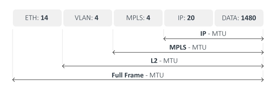 | Mikrotik RouterOS recognizes several types of MTU:
|
Full frame MTU
Full frame MTU represents the actual size of the frame that is transmitted by a particular interface. The Frame Checksum (FCS) is not included in this value, as it is removed by the Ethernet driver as soon as the frame reaches its destination.
MAC/Layer-2/L2 MTU
L2MTU indicates the maximum size of the frame without the MAC header that can be sent by this interface.
In RouterOS L2MTU values can be seen in the "/interface" menu. L2MTU support is added for all Routerboard-related Ethernet interfaces, VLANs, Bridge, VPLS, and wireless interfaces. Some of them support the configuration of the L2MTU value. All other Ethernet interfaces might indicate L2MTU only if the chipset is the same as Routerboard Ethernets.
This will allow users to check if the desired setup is possible. Users will be able to utilize additional bytes for VLAN and MPLS tags, or simply increase interface MTU to get rid of some unnecessary fragmentation.
This table shows the max-l2mtu supported by Mikrotik RouterBoards (available in the /interface/print menu as the value of the read-only "max-l2mtu" option):
| Model name | MTU description |
| RB SXT series, RB LHG, RB LDF, PL6411-2nD, PL7411-2nD, RB711 series, wAP R-2nD, RB912R-2nD-LTm (LtAP mini), RB Metal series, RB SXT Lite series, RB Groove series, Cube Lite60, LHG Lite60 | ether1:2028 |
| RB SXT G series, RB DynaDish, wAP ac, RB QRT series, RB711G series, RB911G, RB912UAG | ether1:4076 |
| RB OmniTik series, RB750, RB750UP, RB751U-2HnD, RB951-2n | ether1:4076; ether2-ether5:2028 |
| RB OmniTik ac series, RB750GL, RB750Gr2 | ether1-ether5:4074 |
| RB mAP, RB mAP lite, RB cAP, RB wAP | ether1-ether2:2028 |
| RB750r2, RB750P-PBr2, RB750UPr2, RB941-2nD, RB951Ui/RB952Ui series | ether1-ether5:2028 |
| RB750Gr3 | ether1-ether5:2026 |
| RB751G-2HnD, RB951G-2HnD | ether1-ether5:4074 |
| RB962UiGS, RB960PGS | ether1-ether5:4074; sfp1:4076 |
| RB LHGG series | ether1:9214 |
| LHG XL 52 ac | ether1:9214; sfp1:9214 |
| RB1100Hx2, RB1100AHx2 | ether1-ether10:9498; ether11:9500; ether12-ether13:9116 |
| RB4011iGS+ series | ether1-ether10:9578; sfp-sfpplus1:9982 |
| CCR1009 series | ether1-ether4:10224; ether5-ether8:10226; sfp1:10226; sfp-sfpplus1:10226 |
| CCR1016 series | ether1-ether12:10226; sfp1-sfp12:10226; sfp-sfpplus1:10226 |
| CCR1036 series | ether1-ether12:10226; sfp1-sfp4:10226; sfp-sfpplus1-sfp-sfpplus2:10226 |
| CCR1072 series | ether1:9116; sfp-sfpplus1-sfp-sfpplus8:10226 |
| CCR2004-1G-12S+2XS | ether1:9586; sfp-sfpplus1-sfp-sfpplus12:9578; sfp28-1 - sfp28-2:9578 |
| CCR2004-16G-2S+ | ether1-ether16:9582; sfp-sfpplus1-sfp-sfpplus2:9586 |
| CCR2116-12G-4S+ | ether1-ether12:9570; ether13:9586; sfp-sfpplus1-sfp-sfpplus4:9570 |
| CCR2216-1G-12XS-2XQ | ether1:9586; sfp28-1 - sfp28-12:9570; qsfp28-1-1 - qsfp28-2-4:9570 |
| CRS109-8G-1S | ether1-ether8:4064; sfp1:4064 |
| CRS125-24G-1S | ether1-ether24:4064; sfp1:4064 |
| CRS112-8G-4S, CRS112-8P-4S | ether1-ether8:9204; sfp9-sfp12:9204 |
| CRS106-1C-5S | sfp1-sfp5:9204; combo1:9204 |
| CRS210-8G-2S+ | ether1-ether8:9204; sfp-sfpplus1:9204; sfpplus2:9204 |
| CRS212-1G-10S-1S+ | ether1:9204; sfp1-sfp10:9204; sfpplus1:9204 |
| CRS226-24G-2S+ | ether1-ether24:9204; sfp-sfpplus1:9204; sfpplus2:9204 |
| CRS326-24G-2S+, CSS326-24G-2S+ | ether1-ether24:10218; sfp-sfpplus1:10218; sfpplus2:10218 |
| CRS317-1G-16S+ | ether1:10218; sfp-sfpplus1-sfp-sfpplus16:10218 |
| CRS328-24P-4S+ | ether1-ether24:10218; sfp-sfpplus1-sfp-sfpplus4:10218 |
| CRS328-4C-20S-4S+ | combo1-combo4:10218; sfp1-sfp20:10218; sfp-sfpplus1-sfp-sfpplus4:10218 |
| CRS305-1G-4S+ | ether1:10218; sfp-sfpplus1-sfp-sfpplus4:10218 |
| CRS304-4XG | ether1-ether4:10218; ether5:9676 |
| CRS309-1G-8S+ | ether1:10218; sfp-sfpplus1-sfp-sfpplus8:10218 |
| netFiber 9/IN (CRS310-1G-5S-4S+) | sfp1-sfp5:10218; sfp-sfpplus1-sfp-sfpplus4:10218 |
| CRS310-8G+2S+IN | ether1-ether8:10218; sfp-sfpplus1-sfp-sfpplus2:10218 |
| CRS312-4C+8XG | combo1-combo4:10218; ether1-ether8:10218; ether9:2028 |
| netPower 15FR (CRS318-1Fi-15Fr-2S) | ether1-ether16:10218; sfp1-sfp2:10218 |
| netPower 16P (CRS318-16P-2S+) | ether1-ether16:10218; sfp-sfpplus1-sfp-sfpplus2:10218 |
| CRS326-4C+20G+2Q+ | combo1-combo4:10218; ether1-ether20:10218; qsfpplus1-1-qsfpplus2-4:10218; ether21:2028 |
| CRS326-24S+2Q+ | sfp-sfpplus1-sfp-sfpplus24:10218; qsfpplus1-1-qsfpplus2-4:10218; ether1:2028 |
| CRS354-48G-4S+2Q+, CRS354-48P-4S+2Q+ | sfp-sfpplus1-sfp-sfpplus4:10218; qsfpplus1-1-qsfpplus2-4:10218; ether1-ether48:10218; ether49:2028 |
| CRS418-8P-8G-2S+RM | ether1-ether16:10218; ether17:9018; sfp-sfpplus1-sfp-sfpplus2: 10218 |
| CRS504-4XQ-IN | ether1:2028; qsfp28-1-1 - qsfp28-4-4:10218 |
| CRS510-8XS-2XQ-IN | ether1:2028; sfp28-1 - sfp28-8:10218; qsfp28-1-1 - qsfp28-2-4:10218 |
| CRS518-16XS-2XQ | ether1:2028; sfp28-1 - sfp28-16:10218; qsfp28-1-1 - qsfp28-2-4:10218 |
| CRS812-8DS-2DQ-2DDQ-RM | ether1-ether2:9586; qsfp56-1-1 - qsfp56-2-4:9570; qsfp56-dd-1-1 - qsfp56-dd-2-8:9570; sfp56-1 - sfp56-8:9570 |
| CSS610-8G-2S+, CSS610-8P-2S+ | ether1-ether8:10218; sfp-sfpplus1-sfp-sfpplus2:10218 |
| D52G-5HacD2HnD (hAP ac²) | ether1-ether5:9124 |
| C52iG-5HaxD2HaxD (hAP ax[^2]) | ether1-ether5:9214 |
| C53UiG+5HPaxD2HPaxD (hAP ax[^3]) | ether1-ether5:9214 |
| L41G-2axD (hAP ax lite) | ether1-ether4:2026 |
| cAP ac | ether1-ether2:9124 |
| GPEN21 | ether1-ether2:10222; sfp1: 10222 |
| wAP60G, LHG60G | ether1:9124 |
| RB260GS series, CSS106-5G-1S, CSS106-1G-4P-1S | ether1-ether5:9198; sfp1:9198 |
| RBFTC11 | ether1:4046; sfp1:4046 |
| RBM33G | ether1-ether3:2026 |
| RBM11G | ether1:2026 |
| RB760iGS | ether1-ether5:2026; sfp1:2026 |
| E50UG | ether1:2048; ether2-ether5:2026 |
| RB411 series | ether1:1526 |
| RB433 series, RB450, RB493 series | ether1:1526; ether2-ether3:1522 |
| RB450Gx4 | ether1-ether5:9214 |
| RB411GL | ether1:1520 |
| RB433GL, RB435G, RB450G, RB493G | ether1-ether3:1520 |
| RB800 | ether1-ether2:9500; ether3:9116 |
| RB850Gx2 | ether1-ether5:1580 |
| RB921UAGS, RB922UAGS | ether1:4076; sfp1:4076 |
| D23UGS-5HPacD2HnD (NetMetal ac²) | ether1:9214; sfp1:9214 |
| L23UGSR-5HaxD2HaxD (NetMetal ax) | ether1:8158; sfp1:8158 |
| RB953GS | ether1-ether2:4074; sfp1:4074; sfp2:4076 |
| RB2011 series | ether1-ether5:4074; ether6-ether10:2028; sfp1:4074 |
| RB3011 series | ether1-ether5:8156; ether6-ether10:8156; sfp1:8158 |
| RB5009 series | ether1-ether8: 9796; sfp-sfpplus1: 9796 |
| L009 series | ether1: 8158; ether2-ether8: 8154; sfp1: 8154 |
| RB44Ge | ether1-ether4:9116 |
All wireless interfaces in RouterOS (including Nstreme2) support 2290 byte L2MTU.
L2MTU configuration changes trigger all interface reloads (link down/link up) due to necessary internal processes.
It is recommended to configure L2MTU with caution by keeping in mind that it can cause short interruption to connected devices.
MPLS/Layer-2.5/L2.5 MTU
The MPLS MTU is configured in the /mpls/interface menu and specifies the maximum packet size, including MPLS labels, that can be sent out through a particular interface.
Ensure that the MPLS MTU value is smaller than or equal to the L2MTU. The MPLS MTU affects packets differently depending on the action the MPLS router is performing. It is strongly recommended that the same MPLS MTU value is configured on all routers forming the MPLS cloud, due to the effects MPLS MTU has on MPLS-switched packets. This requirement means that all interfaces participating in the MPLS cloud must be configured with the smallest MPLS MTU value among the participating interfaces; therefore, careful consideration must be taken when selecting the hardware to be used.
You can read more about MPLS MTU here.
MPLS Switching
When a packet that includes MPLS labels(s) exceeds the configured MPLS MTU, the router attempts to determine the protocol type carried inside the MPLS frame:
-
IP packets: If the encapsulated packet is an IP packet, MPLS generates an ICMP "Need Fragmentation" error message. This behavior mirrors standard IP protocol handling. Note that this ICMP error is not routed directly back to the packet originator; instead, it is switched toward the end of the Label Switched Path (LSP), allowing the egress router to route it back to the source.
-
Non-IP packets: If the encapsulated packet is not an IP packet, MPLS simply discards it because the router cannot interpret the packet contents. This behavior is particularly important for MPLS applications such as VPLS, where frames passing through the MPLS network are not IP packets but rather encapsulated Ethernet frames. If the MPLS MTU configured on any interface along the LSP is smaller than the packet size prepared by the ingress router, the frames will be dropped silently.
IP ingress
When a router initially pushes a label onto an IP packet, and the resulting packet size including the MPLS label exceeds the MPLS MTU, the router behaves as if the interface MTU was exceeded. It will either fragment the packet into fragments that do not exceed the MPLS MTU when labels are attached (if the IP Don't Fragment bit is not set) or generate an ICMP Need Fragmentation error that is sent back to the originator.
VPLS ingress
When the router encapsulates an Ethernet frame for forwarding over a VPLS pseudowire, it checks whether the packet size, including the VPLS Control Word (4 bytes) and any necessary label (typically 2 labels, which adds 8 bytes), exceeds the MPLS MTU of the outgoing interface. If it does, VPLS fragments packets so that they honor the MPLS MTU of the outgoing interface. The packet is reassembled at the egress point of the VPLS pseudowire.
Setup Examples
In these examples, we will take a look at frames entering and leaving the router via Ethernet interfaces.
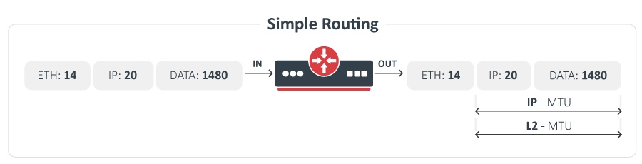
Simple Routing
The image shows the packet MTU size for simple routing, packet size is not modified.
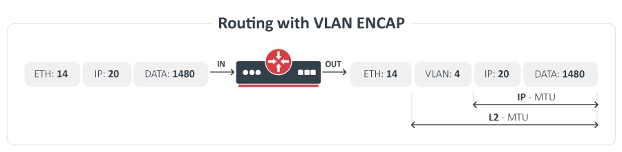
Routing with VLAN Encap
Each VLAN tag is 4 bytes long. The VLAN tag is added by a router. L2-MTU is increased by 4 bytes.
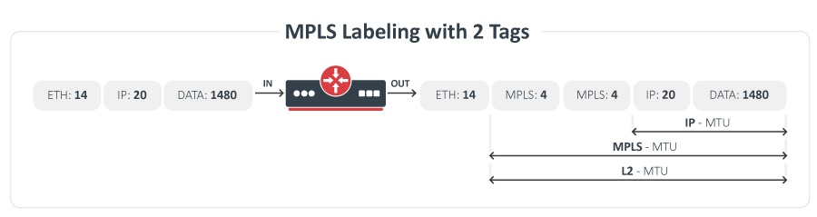
Simple MPLS with Tags
When MPLS is used as a plain replacement for IP routing, only one label is attached to every packet, therefore packet size increases by 4 bytes. We have the situation with two MPLS labels. In order to be able to forward standard size (1500 bytes) IP packets without fragmentation, MPLS MTU must be set to at least 1508 for two MPLS labels.
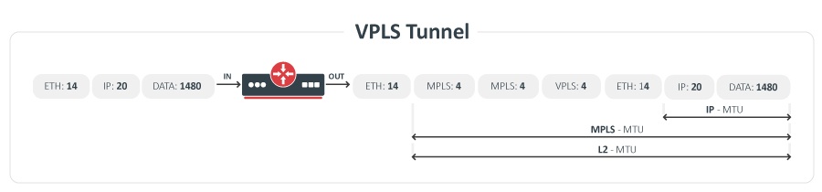
VPLS Tunnel
Two MPLS labels are present when a remote endpoint is not directly attached. One MPLS label is used to get to a remote endpoint; the second label is used to identify the VPLS tunnel.
Advanced Setup Examples
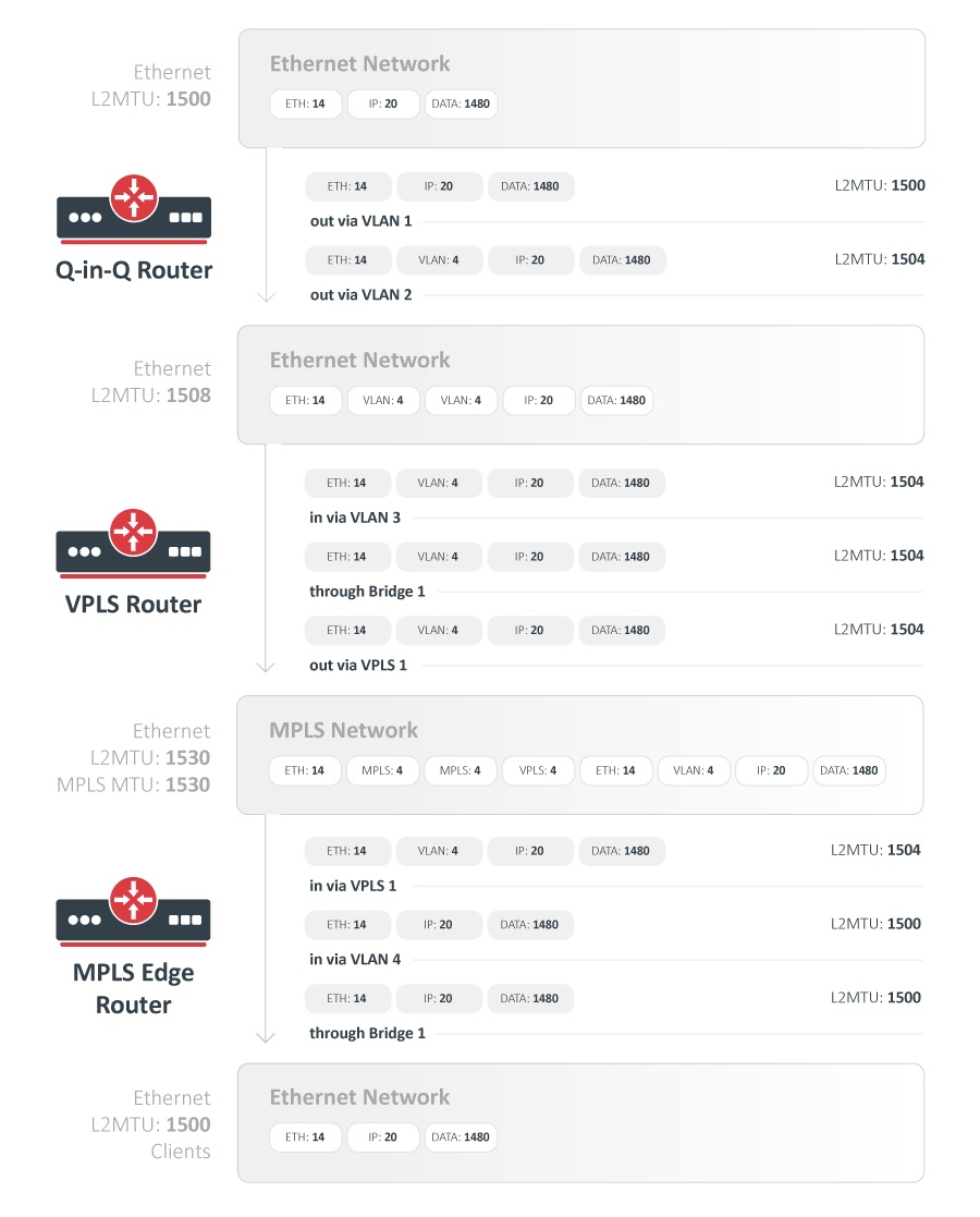
In this example, we will take a closer look at the required L2MTU of all Ethernet-like interfaces including Bridge, VLAN, and VPLS interfaces.
In this setup we will have 3 routers:
-
Q-in-Q router - this router will receive a standard 1500 byte Ethernet frame and will add two VLAN tags to the packet. Then the packet will be sent out via an Ethernet network to the second router.
-
VPLS router - this router will remove the outer VLAN tag and will bridge the packet with the remaining VLAN tag with the VPLS tunnel. The VPLS tunnel will take a packet through the MPLS network to the third router.
-
MPLS Edge router - will remove VPLS and VLAN tags and bridge the packet to the client Ethernet network.